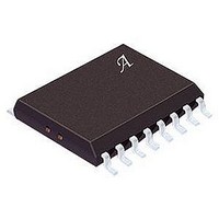
ACS710KLATR-12CB-T Allegro Microsystems Inc, ACS710KLATR-12CB-T Datasheet - Page 13

ACS710KLATR-12CB-T
Manufacturer Part Number
ACS710KLATR-12CB-T
Description
IC, CURRENT SENSOR, 11mA, 16-SOIC
Manufacturer
Allegro Microsystems Inc
Series
-r
Datasheet
1.ACS710KLATR-12CB-T.pdf
(17 pages)
Specifications of ACS710KLATR-12CB-T
Quiescent Current
11mA
Bandwidth
120kHz
Sensor Case Style
SOIC
No. Of Pins
16
Supply Voltage Range
3V To 5.5V
Operating Temperature Range
-40°C To +125°C
Termination Type
SMD
Featured Product
ACS710 Current Sensor IC
Current - Sensing
±12.5A
Accuracy
±3.05%
Sensitivity
56mV/A
Current - Supply
11mA
Sensor Type
Hall Effect
Voltage - Supply
3 V ~ 5.5 V
Output
2.5V
Frequency
120kHz
Response Time
4µs
Polarization
Bidirectional
Operating Temperature
-40°C ~ 125°C
Package / Case
16-SOIC (0.295", 7.50mm Width)
Accuracy %
0.75%
Filter Terminals
SMD
Rohs Compliant
Yes
Lead Free Status / RoHS Status
Lead free / RoHS Compliant
Available stocks
Company
Part Number
Manufacturer
Quantity
Price
Company:
Part Number:
ACS710KLATR-12CB-T
Manufacturer:
IR
Quantity:
3 100
Part Number:
ACS710KLATR-12CB-T
Manufacturer:
ALLEGRO/雅丽高
Quantity:
20 000
ACS710
5. The ¯ F ¯ ¯ A ¯ ¯ U ¯ ¯ L ¯ ¯ T ¯ pin did not reach the 2 V latch point before the
Chopper Stabilization Technique
Chopper Stabilization is an innovative circuit technique that is
used to minimize the offset voltage of a Hall element and an asso-
ciated on-chip amplifier. Allegro patented a Chopper Stabiliza-
6. This curve shows V
7. When the FAULT_EN pin is brought low, if the fault condition
8. At this point there is a fault condition, and the part is enabled
OC fault condition cleared. Because of this, the fixed 3 mA
current sink turns off, and the internal PMOS pull-up turns on
to recharge C
through the internal PMOS pull-up. The slope is determined
by C
still exists, the latched ¯ F ¯ ¯ A ¯ ¯ U ¯ ¯ L ¯ ¯ T ¯ pin will be pulled low by the
internal 3mA current source. When fault condition is removed
then the Fault pin charges as shown in step 6.
before the ¯ F ¯ ¯ A ¯ ¯ U ¯ ¯ L ¯ ¯ T ¯ pin can charge to V
user-set delay, so the fault is latched earlier. The new delay
time can be calculated by equation 1, after substituting the
voltage seen on the ¯ F ¯ ¯ A ¯ ¯ U ¯ ¯ L ¯ ¯ T ¯ pin for V
OC
.
OC
through the ¯ F ¯ ¯ A ¯ ¯ U ¯ ¯ L ¯ ¯ T ¯ pin.
CC
charging external capacitor C
Hall Element
Current Sensor with Integrated Overcurrent Detection
CC
CC
.
. This shortens the
Regulator
Concept of Chopper Stabilization Technique
OC
120 kHz Bandwidth, High Voltage Isolation
tion technique that nearly eliminates Hall IC output drift induced
by temperature or package stress effects. This offset reduction
technique is based on a signal modulation-demodulation process.
Modulation is used to separate the undesired dc offset signal from
the magnetically induced signal in the frequency domain. Then,
using a low-pass filter, the modulated DC offset is suppressed
while the magnetically induced signal passes through the filter.
As a result of this chopper stabilization approach, the output
voltage from the Hall IC is desensitized to the effects of tempera-
ture and mechanical stress. This technique produces devices that
have an extremely stable Electrical Offset Voltage, are immune to
thermal stress, and have precise recoverability after temperature
cycling.
This technique is made possible through the use of a BiCMOS
process that allows the use of low-offset and low-noise amplifiers
in combination with high-density logic integration and sample
and hold circuits.
Clock/Logic
Amp
Low-Pass
Filter
115 Northeast Cutoff
1.508.853.5000; www.allegromicro.com
Allegro MicroSystems, Inc.
Worcester, Massachusetts 01615-0036 U.S.A.
13


