DG406DJ Vishay, DG406DJ Datasheet - Page 4
DG406DJ
Manufacturer Part Number
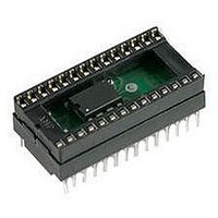
DG406DJ
Description
IC, ANALOG MULTIPLEXER, 16 X 1, DIP-28
Manufacturer
Vishay
Type
Analog Multiplexerr
Datasheet
1.DG406DN-T1-E3.pdf
(11 pages)
Specifications of DG406DJ
No. Of Circuits
1
Supply Current
50µA
On State Resistance Max
125ohm
Supply Voltage Range
± 5V To ± 20V
Operating Temperature Range
-40°C To +85°C
Analog Switch Case Style
DIP
Package
28PDIP
Maximum On Resistance
120@12V Ohm
Maximum Propagation Delay Bus To Bus
350@±15V ns
Maximum High Level Output Current
30 mA
Multiplexer Architecture
16:1
Maximum Turn-off Time
300@12V ns
Maximum Turn-on Time
600@12V ns
Power Supply Type
Single|Dual
Lead Free Status / RoHS Status
Contains lead / RoHS non-compliant
Available stocks
Company
Part Number
Manufacturer
Quantity
Price

Part Number:
DG406DJ
Manufacturer:
INTERSIL
Quantity:
20 000
Company:
Part Number:
DG406DJ+
Manufacturer:
Maxim Integrated Products
Quantity:
135
Company:
Part Number:
DG406DJ+
Manufacturer:
Vishay
Quantity:
10 105
Company:
Part Number:
DG406DJZ
Manufacturer:
Intersil
Quantity:
2 002


DG406, DG407
Vishay Siliconix
www.vishay.com
4
SPECIFICATIONS
Parameter
Analog Switch
Analog Signal Range
Drain-Source
On-Resistance
R
Channels
Source Off Leakage Current
Drain Off Leakage Current
Drain On Leakage Current
Digital Control
Logic High Input Voltage
Logic Low Input Voltage
Logic High Input Current
Logic Low Input Current
Logic Input Capacitance
Dynamic Characteristics
Transition Time
Break-Before-Make Interval
Enable Turn-On Time
Enable Turn-Off Time
Charge Injection
Off Isolation
Source Off Capacitance
Drain Off Capacitance
Drain On Capacitance
Power Supplies
Positive Supply Current
Negative Supply Current
Positive Supply Current
Negative Supply Current
DS(on)
Matching Between
g
h
e
a
V
R
Symbol
t
R
t
t
OFF(EN)
ANALOG
C
C
C
t
ON(EN)
OIRR
TRANS
I
I
I
V
V
OPEN
DS(on)
D(off)
D(on)
S(off)
I
C
D(off)
D(on)
DS(on)
I
S(off)
I+
I+
INH
AH
AL
Q
INL
I-
I-
in
V
Unless Otherwise Specified
V
EN
S
V
V
sequence each switch on
sequence each
V
V
EN
= 0 V, C
D
V+ = 15 V, V- = - 15 V
AL
V
S
V
V
= 0 V, V
V
V
V
V
f = 1 MHz
switch on
= ± 10 V, I
D
EN
S
V
= V
EN
Test Conditions
EN
= 0 V, 2.4 V, V
EN
EN
= 0.8 V, V
V
D
= ± 10 V
= ± 10 V
A
V
= 2.4 V, V
see figure 2
see figure 4
see figure 3
= 0 V, R
f = 100 kHz
= 0 V
D
= V
= 0 V
= 0 V
= 2.4 V, 15 V
f = 1 MHz
D
= ± 10
L
S
= ± 10 V
A
= 1 nF, R
= 0 V, f = 1 MHz
= 0 or 5 V
S
AH
L
= - 10 mA
A
= 1 k
= 2.4 V
= 0 V
A
S
= 0 V
DG406
DG407
DG406
DG407
DG407
DG406
DG407
= 0
f
Temp.
Room
Room
Room
Room
Room
Room
Room
Room
Room
Room
Room
Room
Room
Room
Room
Room
Room
Room
Room
Room
Room
Room
Room
Full
Full
Full
Full
Full
Full
Full
Full
Full
Full
Full
Full
Full
Full
Full
Full
Full
Full
Full
b
- 0.01
- 0.01
Typ.
0.01
0.04
0.04
0.04
0.04
200
150
- 69
130
140
50
50
70
15
65
70
13
50
5
7
8
c
- 55 °C to 125 °C
Min.
- 200
- 100
- 200
- 100
- 0.5
- 15
- 50
- 10
- 20
- 20
2.4
- 1
- 1
- 1
- 1
- 1
- 1
- 1
25
10
A Suffix
d
Max.
100
125
200
100
200
100
350
450
200
400
150
300
500
900
0.5
0.8
15
50
30
75
1
1
1
1
1
1
S11-0179-Rev. J, 07-Feb-11
d
Document Number: 70061
- 40 °C to 85 °C
Min.
- 0.5
- 15
- 40
- 20
- 40
- 20
- 10
- 20
- 20
2.4
- 5
- 1
- 1
- 1
- 1
- 1
- 1
25
10
- 1
D Suffix
d
Max.
100
125
350
450
200
400
150
300
500
700
0.5
0.8
15
40
20
40
20
30
75
5
1
1
1
1
1
1
d
Unit
nA
µA
pF
pC
dB
pF
µA
ns
%
V
V
Related parts for DG406DJ
Image
Part Number
Description
Manufacturer
Datasheet
Request
R

Part Number:
Description:
DG406 Multiplexer Optimizes Medical Simulator
Manufacturer:
Vishay Semiconductors
Datasheet:

Part Number:
Description:
357-036-542-201 CARDEDGE 36POS DL .156 BLK LOPRO
Manufacturer:
Vishay
Datasheet:
Part Number:
Description:
357-036-542-201 CARDEDGE 36POS DL .156 BLK LOPRO
Manufacturer:
Vishay
Datasheet:
Part Number:
Description:
357-036-542-201 CARDEDGE 36POS DL .156 BLK LOPRO
Manufacturer:
Vishay
Datasheet:
Part Number:
Description:
357-036-542-201 CARDEDGE 36POS DL .156 BLK LOPRO
Manufacturer:
Vishay
Datasheet:
Part Number:
Description:
357-036-542-201 CARDEDGE 36POS DL .156 BLK LOPRO
Manufacturer:
Vishay
Datasheet:
Part Number:
Description:
357-036-542-201 CARDEDGE 36POS DL .156 BLK LOPRO
Manufacturer:
Vishay
Datasheet:
Part Number:
Description:
357-036-542-201 CARDEDGE 36POS DL .156 BLK LOPRO
Manufacturer:
Vishay
Datasheet:
Part Number:
Description:
357-036-542-201 CARDEDGE 36POS DL .156 BLK LOPRO
Manufacturer:
Vishay
Datasheet:
Part Number:
Description:
357-036-542-201 CARDEDGE 36POS DL .156 BLK LOPRO
Manufacturer:
Vishay
Datasheet:
Part Number:
Description:
357-036-542-201 CARDEDGE 36POS DL .156 BLK LOPRO
Manufacturer:
Vishay
Datasheet:
Part Number:
Description:
357-036-542-201 CARDEDGE 36POS DL .156 BLK LOPRO
Manufacturer:
Vishay
Datasheet:
Part Number:
Description:
357-036-542-201 CARDEDGE 36POS DL .156 BLK LOPRO
Manufacturer:
Vishay
Datasheet:
Part Number:
Description:
357-036-542-201 CARDEDGE 36POS DL .156 BLK LOPRO
Manufacturer:
Vishay
Datasheet:
Part Number:
Description:
357-036-542-201 CARDEDGE 36POS DL .156 BLK LOPRO
Manufacturer:
Vishay
Datasheet: