AD590JRZ Analog Devices Inc, AD590JRZ Datasheet - Page 6
AD590JRZ
Manufacturer Part Number
AD590JRZ
Description
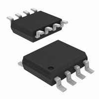
IC,TEMPERATURE SENSOR,BIPOLAR/JFET,SOP,8PIN,PLASTIC
Manufacturer
Analog Devices Inc
Datasheet
1.AD590JH.pdf
(16 pages)
Specifications of AD590JRZ
Rohs Compliant
YES
Sensing Temperature
-55°C ~ 150°C
Output Type
Current
Voltage - Supply
4 V ~ 30 V
Accuracy
±5°C
Package / Case
8-SOIC (0.154", 3.90mm Width)
Ic Output Type
Current
Supply Voltage Range
4V To 30V
Resolution (bits)
8bit
Sensor Case Style
SOIC
No. Of Pins
8
Peak Reflow Compatible (260 C)
Yes
Supply Voltage Max
30V
Supply Voltage Min
4V
Lead Free Status / RoHS Status
Lead free / RoHS Compliant
Available stocks
Company
Part Number
Manufacturer
Quantity
Price

Part Number:
AD590JRZ
Manufacturer:
ADI/亚德诺
Quantity:
20 000


AD590
PRODUCT DESCRIPTION
The AD590 is a 2-terminal temperature-to-voltage transducer. It
is available in a variety of accuracy grades and packages. When
using the AD590 in die form, the chip substrate must be kept
electrically isolated (floating) for correct circuit operation.
The AD590 uses a fundamental property of the silicon
transistors from which it is made to realize its temperature
proportional characteristic: if two identical transistors are
operated at a constant ratio of collector current densities, r,
then the difference in their base-emitter voltage is (kT/q)(In r).
Because both k (Boltzman’s constant) and q (the charge of an
electron) are constant, the resulting voltage is directly
proportional to absolute temperature (PTAT).
In the AD590, this PTAT voltage is converted to a PTAT current
by low temperature coefficient thin-film resistors. The total
current of the device is then forced to be a multiple of this
PTAT current. Figure 6 is the schematic diagram of the AD590.
In this figure, Q8 and Q11 are the transistors that produce the
PTAT voltage. R5 and R6 convert the voltage to current. Q10,
whose collector current tracks the collector currents in Q9 and
Q11, supplies all the bias and substrate leakage current for the
rest of the circuit, forcing the total current to be PTAT. R5 and
R6 are laser-trimmed on the wafer to calibrate the device at 25°C.
V+
V–
THE AD590 IS AVAILABLE IN LASER-TRIMMED CHIP FORM;
CONSULT THE CHIP CATALOG FOR DETAILS
Figure 5. Metallization Diagram
66MILS
1
42MILS
Rev. E | Page 6 of 16
Figure 7 shows the typical V–I characteristic of the circuit at
25°C and the temperature extremes.
1
For a more detailed description, see M.P. Timko, “A Two-Terminal IC
Temperature Transducer,” IEEE J. Solid State Circuits, Vol. SC-11, p. 784-788,
Dec. 1976. Understanding the Specifications–AD590.
423
298
218
0
Q1
8
1
R6
820Ω
SUBSTRATE
Q9
Figure 6. Schematic Diagram
2
Q7
Q2
CHIP
Figure 7. V–I Plot
Q6
SUPPLY VOLTAGE (V)
–
3
146Ω
Q12
R5
R3
5kΩ
+
R1
260Ω
Q5
Q10
1
4
R4
11kΩ
R2
1040Ω
26pF
Q3
C1
Q8
5
+150°C
+25°C
–55°C
Q11
Q4
6
1
30
Related parts for AD590JRZ
Image
Part Number
Description
Manufacturer
Datasheet
Request
R

Part Number:
Description:
±1.7g Dual-Axis IMEMS Accelerometer Evaluation Board
Manufacturer:
Analog Devices Inc
Datasheet:

Part Number:
Description:
Inertial Sensor Evaluation System
Manufacturer:
Analog Devices Inc
Datasheet:
Part Number:
Description:
Manufacturer:
Analog Devices Inc
Datasheet:
Part Number:
Description:
Manufacturer:
Analog Devices Inc
Datasheet:
Part Number:
Description:
Manufacturer:
Analog Devices Inc
Datasheet:
Part Number:
Description:
Manufacturer:
Analog Devices Inc
Datasheet:
Part Number:
Description:
Manufacturer:
Analog Devices Inc
Datasheet:
Part Number:
Description:
Manufacturer:
Analog Devices Inc
Datasheet:
Part Number:
Description:
Manufacturer:
Analog Devices Inc
Datasheet:
Part Number:
Description:
Manufacturer:
Analog Devices Inc
Datasheet:
Part Number:
Description:
Manufacturer:
Analog Devices Inc
Datasheet:
Part Number:
Description:
Manufacturer:
Analog Devices Inc
Datasheet:
Part Number:
Description:
Manufacturer:
Analog Devices Inc
Datasheet: