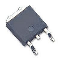
LM2930S-5.0 National Semiconductor, LM2930S-5.0 Datasheet - Page 3

LM2930S-5.0
Manufacturer Part Number
LM2930S-5.0
Description
V REG LDO +5.0V, SMD, 2930, TO2633
Manufacturer
National Semiconductor
Datasheet
1.LM2930S-5.0.pdf
(10 pages)
Specifications of LM2930S-5.0
Output Voltage
5V
Dropout Voltage Vdo
0.32V
No. Of Pins
3
Voltage Regulator Case Style
TO-263
Operating Temperature Range
-40°C To +85°C
Svhc
No SVHC (15-Dec-2010)
Operating Temperature
RoHS Compliant
Output Voltage Fixed
5V
Rohs Compliant
Yes
Available stocks
Company
Part Number
Manufacturer
Quantity
Price
Company:
Part Number:
LM2930S-5.0
Manufacturer:
NS
Quantity:
500
Current Limit
Dropout Voltage
Output Voltage Under
Transient Conditions
Electrical Characteristics
LM2930-8.0 (V
Note 1: Absolute Maximum Ratings indicate limits beyond which damage to the device may occur. Operating ratings indicate conditions for which the device is
functional, but do not guarantee specific performance limits. Electrical Characteristics state DC and AC electrical specifications under particular test conditions which
guarantee specific performance limits. This assumes that the device is within the Operating Ratings. Specifications are not guaranteed for parameters where no limit
is given, however, the typical value is a good indication of device performance.
Note 2: Thermal resistance without a heat sink for junction to case temperature is 3˚C/W and for case to ambient temperature is 50˚C/W for the TO-220, 73˚C/W
for the TO-263. If the TO-263 package is used, the thermal resistance can be reduced by increasing the P.C. board copper area thermally connected to the package.
Using 0.5 square inches of copper area, θ
is 32˚C/W.
Note 3: All characteristics are measured with a capacitor across the input of 0.1 µF and a capacitor across the output of 10 µF. All characteristics except noise
voltage and ripple rejection ratio are measured using pulse techniques (t
must be taken into account separately.
Note 4: Guaranteed and 100% production tested.
Note 5: Guaranteed (but not 100% production tested) over the operating temperature and input current ranges. These limits are not used to calculate outgoing
quality levels.
Note 6: To ensure constant junction temperature, low duty cycle pulse testing is used.
Typical Application
*Required if regulator is located far from power supply filter.
**C
regulator. This capacitor must be rated over the same operating temperature range as the regulator. The equivalent series resistance (ESR) of this capacitor
should be less than 1Ω over the expected operating temperature range.
Typical Performance Characteristics
OUT
Parameter
must be at least 10 µF to maintain stability. May be increased without bound to maintain regulation during transients. Locate as close as possible to the
IN
=14V, I
Output Impedance
O
=150 mA, T
I
−12V≤V
O
=150 mA
JA
IN
is 50˚C/W; with 1 square inch of copper area, θ
≤40V, R
j
=25˚C (Note 6), C2=10 µF, unless otherwise specified)
Conditions
(Note 3) (Continued)
L
=100Ω
00553911
W
≤10 ms, duty cycle≤5%). Output voltage changes due to changes in internal temperature
3
JA
0.32
Typ
400
is 37˚C/W; and with 1.6 or more square inches of copper area, θ
Overvoltage Supply Current
(Note 4)
Tested
Limit
−0.3
00553905
700
150
0.6
8.8
(Note 5)
Design
Limit
00553912
www.national.com
mA
mA
V
V
V
Unit
MAX
MAX
MIN
MAX
MIN
JA


