LM1876TF National Semiconductor, LM1876TF Datasheet - Page 12
LM1876TF
Manufacturer Part Number
LM1876TF
Description
Audio Power Amplifier IC
Manufacturer
National Semiconductor
Specifications of LM1876TF
No. Of Channels
2
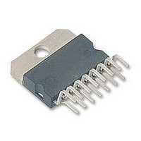
Amplifier Case Style
TO-220
No. Of Pins
15
Termination Type
Through Hole
Mounting Type
Through Hole
Peak Reflow Compatible (260 C)
No
Supply Voltage Max
22V
Lead Free Status / RoHS Status
Contains lead / RoHS non-compliant
Available stocks
Company
Part Number
Manufacturer
Quantity
Price

Part Number:
LM1876TF
Manufacturer:
NS/国半
Quantity:
20 000
Company:
Part Number:
LM1876TF/NOPB
Manufacturer:
RAYTHEON
Quantity:
334


www.national.com
Application Information
MUTE MODE
By placing a logic-high voltage on the mute pins, the signal
going into the amplifiers will be muted. If the mute pins are
left floating or connected to a logic-low voltage, the amplifi-
ers will be in a non-muted state. There are two mute pins,
one for each amplifier, so that one channel can be muted
without muting the other if the application requires such a
configuration. Refer to the Typical Performance Character-
istics section for curves concerning Mute Attenuation vs
Mute Pin Voltage.
STANDBY MODE
The standby mode of the LM1876 allows the user to drasti-
cally reduce power consumption when the amplifiers are
idle. By placing a logic-high voltage on the standby pins, the
amplifiers will go into Standby Mode. In this mode, the cur-
rent drawn from the V
total for both amplifiers. The current drawn from the V
ply is typically 4.2 mA. Clearly, there is a significant reduction
in idle power consumption when using the standby mode.
There are two Standby pins, so that one channel can be put
in standby mode without putting the other amplifier in
standby if the application requires such flexibility. Refer to
the Typical Performance Characteristics section for
curves showing Supply Current vs. Standby Pin Voltage for
both supplies.
UNDER-VOLTAGE PROTECTION
Upon system power-up, the under-voltage protection cir-
cuitry allows the power supplies and their corresponding ca-
pacitors to come up close to their full values before turning
on the LM1876 such that no DC output spikes occur. Upon
turn-off, the output of the LM1876 is brought to ground be-
fore the power supplies such that no transients occur at
power-down.
OVER-VOLTAGE PROTECTION
The LM1876 contains over-voltage protection circuitry that
limits the output current to approximately 3.5 Apk while also
providing voltage clamping, though not through internal
clamping diodes. The clamping effect is quite the same,
however, the output transistors are designed to work alter-
nately by sinking large current spikes.
SPiKe PROTECTION
The
peak-temperature stressing of the power transistor array.
The Safe Operating graph in the Typical Performance
Characteristics section shows the area of device operation
where SPiKe Protection Circuitry is not enabled. The wave-
form to the right of the SOA graph exemplifies how the dy-
namic protection will cause waveform distortion when en-
abled.
THERMAL PROTECTION
The LM1876 has a sophisticated thermal protection scheme
to prevent long-term thermal stress of the device. When the
temperature on the die reaches 165˚C, the LM1876 shuts
down. It starts operating again when the die temperature
drops to about 155˚C, but if the temperature again begins to
rise, shutdown will occur again at 165˚C. Therefore, the de-
vice is allowed to heat up to a relatively high temperature if
the fault condition is temporary, but a sustained fault will
cause the device to cycle in a Schmitt Trigger fashion be-
LM1876
is
CC
protected
supply is typically less than 10 µA
from
instantaneous
EE
sup-
12
tween the thermal shutdown temperature limits of 165˚C and
155˚C. This greatly reduces the stress imposed on the IC by
thermal cycling, which in turn improves its reliability under
sustained fault conditions.
Since the die temperature is directly dependent upon the
heat sink used, the heat sink should be chosen such that
thermal shutdown will not be reached during normal opera-
tion. Using the best heat sink possible within the cost and
space constraints of the system will improve the long-term
reliability of any power semiconductor device, as discussed
in the Determining the Correct Heat Sink Section.
DETERMlNlNG MAXIMUM POWER DISSIPATION
Power dissipation within the integrated circuit package is a
very important parameter requiring a thorough understand-
ing if optimum power output is to be obtained. An incorrect
maximum power dissipation calculation may result in inad-
equate heat sinking causing thermal shutdown and thus lim-
iting the output power.
Equation (1) exemplifies the theoretical maximum power dis-
sipation point of each amplifier where V
voltage.
Thus by knowing the total supply voltage and rated output
load, the maximum power dissipation point can be calcu-
lated. The package dissipation is twice the number which re-
sults from equation (1) since there are two amplifiers in each
LM1876. Refer to the graphs of Power Dissipation versus
Output Power in the Typical Performance Characteristics
section which show the actual full range of power dissipation
not just the maximum theoretical point that results from
equation (1).
DETERMINING THE CORRECT HEAT SINK
The choice of a heat sink for a high-power audio amplifier is
made entirely to keep the die temperature at a level such
that the thermal protection circuitry does not operate under
normal circumstances.
The thermal resistance from the die (junction) to the outside
air (ambient) is a combination of three thermal resistances,
(junction to case), of the LM1876TF is 2˚C/W and the
LM1876T is 1˚C/W. Using Thermalloy Thermacote thermal
compound, the thermal resistance,
about 0.2˚C/W. Since convection heat flow (power dissipa-
tion) is analogous to current flow, thermal resistance is
analogous to electrical resistance, and temperature drops
are analogous to voltage drops, the power dissipation out of
the LM1876 is equal to the following:
where T
ture and
Once the maximum package power dissipation has been
calculated using equation (1), the maximum thermal resis-
tance,
be calculated. This calculation is made using equation (3)
which is derived by solving for
Again it must be noted that the value of
upon the system designer’s amplifier requirements. If the
ambient temperature that the audio amplifier is to be working
JC
,
CS
SA
SA
JMAX
, and
JA
, (heat sink to ambient) in ˚C/W for a heat sink can
= [(T
=
= 150˚C, T
JMAX
SA
P
JC
DMAX
. In addition, the thermal resistance,
P
+
−T
DMAX
CS
AMB
= (T
AMB
+
= V
)−P
JMAX
is the system ambient tempera-
SA
CC
DMAX
.
SA
−T
2/2
AMB
(
in equation (2).
2
JC
R
CS
)/
CC
L
+
JA
(case to sink), is
is the total supply
CS
SA
)]/P
is dependent
DMAX
(1)
(2)
(3)
JC
Related parts for LM1876TF
Image
Part Number
Description
Manufacturer
Datasheet
Request
R

Part Number:
Description:
National Semiconductor [8-Bit D/A Converter]
Manufacturer:
National Semiconductor
Datasheet:
Part Number:
Description:
National Semiconductor [Media Coprocessor]
Manufacturer:
National Semiconductor
Datasheet:
Part Number:
Description:
Digitally Controlled Tone and Volume Circuit with Stereo Audio Power Amplifier, Microphone Preamp Stage and National 3D Sound
Manufacturer:
National Semiconductor
Datasheet:
Part Number:
Description:
Digitally Controlled Tone and Volume Circuit with Stereo Audio Power Amplifier, Microphone Preamp Stage and National 3D Sound
Manufacturer:
National Semiconductor
Datasheet:
Part Number:
Description:
AC97 Rev 2 Codec with Sample Rate Conversion and National 3D Sound
Manufacturer:
National Semiconductor
Part Number:
Description:
Manufacturer:
National Semiconductor
Datasheet:
Part Number:
Description:
Manufacturer:
National Semiconductor
Datasheet:
Part Number:
Description:
General Purpose, Low Voltage, Low Power, Rail-to-Rail Output Operational Amplifiers
Manufacturer:
National Semiconductor
Datasheet:
Part Number:
Description:
8-bit 20 MSPS flash A/D converter.
Manufacturer:
National Semiconductor
Datasheet:
Part Number:
Description:
Low Noise Quad Operational Amplifier
Manufacturer:
National Semiconductor
Datasheet:
Part Number:
Description:
Quad Differential Line Receivers
Manufacturer:
National Semiconductor
Datasheet:
Part Number:
Description:
Quad High Speed Trapezoidal? Bus Transceiver
Manufacturer:
National Semiconductor
Datasheet:
Part Number:
Description:
Dual Line Receiver
Manufacturer:
National Semiconductor
Datasheet:
Part Number:
Description:
TTL to 10k ECL Level Translator with Latch
Manufacturer:
National Semiconductor
Datasheet: