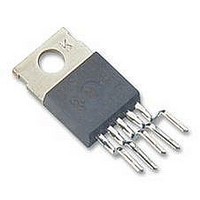
LM2575HVT-5.0 National Semiconductor, LM2575HVT-5.0 Datasheet - Page 13

LM2575HVT-5.0
Manufacturer Part Number
LM2575HVT-5.0
Description
DC/DC Converter IC
Manufacturer
National Semiconductor
Specifications of LM2575HVT-5.0
Input Voltage
60V
Output Voltage
5V
No. Of Pins
5
Termination Type
Through Hole
Mounting Type
Through Hole
Output Current Max
1A
Peak Reflow Compatible (260 C)
No
Supply Voltage Max
60V
Lead Free Status / RoHS Status
Contains lead / RoHS non-compliant
Available stocks
Company
Part Number
Manufacturer
Quantity
Price
Company:
Part Number:
LM2575HVT-5.0
Manufacturer:
NS
Quantity:
500
Part Number:
LM2575HVT-5.0
Manufacturer:
NS/国半
Quantity:
20 000
Given:
V
V
I
F = Switching Frequency (Fixed at 52 kHz)
1. Programming Output Voltage (Selecting R1 and R2, as
shown in Figure 2 )
Use the following formula to select the appropriate resistor
values.
R
cient and stability with time, use 1% metal film resistors)
2. Inductor Selection (L1)
A. Calculate the inductor Volt • microsecond constant,
E • T (V • µs), from the following formula:
B. Use the E • T value from the previous formula and match
it with the E • T number on the vertical axis of the Inductor
Value Selection Guide shown in Figure 7 .
C. On the horizontal axis, select the maximum load current.
D. Identify the inductance region intersected by the E • T
value and the maximum load current value, and note the in-
ductor code for that region.
E. Identify the inductor value from the inductor code, and se-
lect an appropriate inductor from the table shown in Figure 9 .
Part numbers are listed for three inductor manufacturers.
The inductor chosen must be rated for operation at the
LM2575 switching frequency (52 kHz) and for a current rat-
ing of 1.15 x I
the inductor section in the application hints section of this
data sheet.
LOAD
(Continued)
OUT
IN
1
PROCEDURE (Adjustable Output Voltage Versions)
(Max) = Maximum Input Voltage
can be between 1k and 5k. (For best temperature coeffi-
(Max) = Maximum Load Current
= Regulated Output Voltage
LOAD
. For additional inductor information, see
13
Given:
V
V
I
F = 52 kHz
1.Programming Output Voltage (Selecting R1 and R2)
R2 = 1k (8.13 − 1) = 7.13k, closest 1% value is 7.15k
2. Inductor Selection (L1)
A. Calculate E • T (V • µs)
B. E • T = 115 V • µs
C. I
D. Inductance Region = H470
E. Inductor Value = 470 µH Choose from AIE part
# 430-0634, Pulse Engineering part # PE-53118, or Renco
part # RL-1961.
LOAD
OUT
IN
(Max) = 25V
LOAD
EXAMPLE (Adjustable Output Voltage Versions)
(Max) = 1A
= 10V
(Max) = 1A
www.national.com


