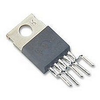
LM2576HVT-5.0 National Semiconductor, LM2576HVT-5.0 Datasheet - Page 19

LM2576HVT-5.0
Manufacturer Part Number
LM2576HVT-5.0
Description
DC/DC Converter IC
Manufacturer
National Semiconductor
Datasheets
1.LM2576SX-5.0.pdf
(24 pages)
2.LM2576SX-5.0.pdf
(24 pages)
3.LM2576SX-5.0.pdf
(22 pages)
Specifications of LM2576HVT-5.0
Input Voltage
60V
Output Voltage
5V
No. Of Pins
5
Termination Type
Through Hole
Mounting Type
Through Hole
Output Current Max
3A
Peak Reflow Compatible (260 C)
No
Supply Voltage Max
60V
Lead Free Status / RoHS Status
Contains lead / RoHS non-compliant
Available stocks
Company
Part Number
Manufacturer
Quantity
Price
Part Number:
LM2576HVT-5.0
Manufacturer:
NS/国半
Quantity:
20 000
Company:
Part Number:
LM2576HVT-5.0/NOPB
Manufacturer:
TI
Quantity:
3 000
Definition of Terms
Most standard aluminum electrolytic capacitors in the
100 µF–1000 µF range have 0.5
Higher-grade capacitors (“low-ESR”, “high-frequency”, or
“low-inductance”) in the 100 µF–1000 µF range generally
have ESR of less than 0.15 .
EQUIVALENT SERIES INDUCTANCE (ESL)
The pure inductance component of a capacitor (see Figure
16 ). The amount of inductance is determined to a large ex-
tent on the capacitor’s construction. In a buck regulator, this
unwanted inductance causes voltage spikes to appear on
the output.
OUTPUT RIPPLE VOLTAGE
The AC component of the switching regulator’s output volt-
age. It is usually dominated by the output capacitor’s ESR
multiplied by the inductor’s ripple current ( I
peak-to-peak value of this sawtooth ripple current can be de-
termined by reading the Inductor Ripple Current section of
the Application hints.
CAPACITOR RIPPLE CURRENT
RMS value of the maximum allowable alternating current at
which a capacitor can be operated continuously at a speci-
fied temperature.
STANDBY QUIESCENT CURRENT (I
Supply current required by the LM2576 when in the standby
mode (ON /OFF pin is driven to TTL-high voltage, thus turn-
ing the output switch OFF).
INDUCTOR RIPPLE CURRENT ( I
The peak-to-peak value of the inductor current waveform,
typically a sawtooth waveform when the regulator is operat-
ing in the continuous mode (vs. discontinuous mode).
CONTINUOUS/DISCONTINUOUS MODE OPERATION
Relates to the inductor current. In the continuous mode, the
inductor current is always flowing and never drops to zero,
vs. the discontinuous mode, where the inductor current
drops to zero for a period of time in the normal switching
cycle.
INDUCTOR SATURATION
The condition which exists when an inductor cannot hold any
more magnetic flux. When an inductor saturates, the induc-
tor appears less inductive and the resistive component domi-
nates. Inductor current is then limited only by the DC resis-
tance of the wire and the available source current.
OPERATING VOLT MICROSECOND CONSTANT (E • T
The product (in VoIt • µs) of the voltage applied to the inductor
and the time the voltage is applied. This E • T
measure of the energy handling capability of an inductor and
is dependent upon the type of core, the core area, the num-
ber of turns, and the duty cycle.
(Continued)
IND
STBY
)
)
to 0.1
op
constant is a
IND
). The
ESR.
op
)
19
Connection Diagrams
Note 15: (XX indicates output voltage option. See ordering information table
for complete part number.)
NS Package Number TS5B, Tape and Reel
LM2576SX-XX or LM2576HVSX-XX
LM2576S-XX or LM2576HVS-XX
LM2576T-XX or LM2576HVT-XX
5-Lead Surface-Mount Package
or LM2576HVT-XX Flow LB03
NS Package Number T05A
NS Package Number TS5B
NS Package Number T05D
LM2576T-XX Flow LB03
Bent, Staggered Leads
5-Lead TO-220 (T)
5-Lead TO-220 (T)
Straight Leads
TO-263 (S)
Top View
Top View
Top View
(Note 15)
DS011476-25
DS011476-21
DS011476-22
www.national.com


