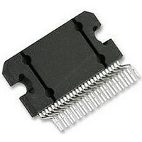
LM4780TA National Semiconductor, LM4780TA Datasheet - Page 4

LM4780TA
Manufacturer Part Number
LM4780TA
Description
Audio Power Amplifier IC
Manufacturer
National Semiconductor
Datasheet
1.LM4780TA.pdf
(26 pages)
Specifications of LM4780TA
Amplifier Case Style
TO-220
Peak Reflow Compatible (260 C)
No
Termination Type
Through Hole
Leaded Process Compatible
No
Package / Case
27-TO-220
Operational Class
Class-AB
Audio Amplifier Output Configuration
1-Channel Mono/2-Channel Stereo
Output Power (typ)
120x1/60x2@8OhmW
Audio Amplifier Function
Speaker
Input Offset Voltage
10mV
Input Bias Current
1uA
Total Harmonic Distortion
0.03@4Ohm@30W%
Single Supply Voltage (typ)
18V
Dual Supply Voltage (typ)
±12/±15/±18/±24/±28V
Power Supply Requirement
Single/Dual
Power Dissipation
125W
Unity Gain Bandwidth Product (typ)
8MHz
Rail/rail I/o Type
No
Power Supply Rejection Ratio
120dB
Single Supply Voltage (min)
20V
Single Supply Voltage (max)
84V
Dual Supply Voltage (min)
±10V
Dual Supply Voltage (max)
±42V
Operating Temp Range
-20C to 85C
Operating Temperature Classification
Commercial
Mounting
Through Hole
Pin Count
27 +Tab
Package Type
TO-220
Lead Free Status / RoHS Status
Contains lead / RoHS non-compliant
Lead Free Status / RoHS Status
Contains lead / RoHS non-compliant
Available stocks
Company
Part Number
Manufacturer
Quantity
Price
Part Number:
LM4780TA L4780TA
Manufacturer:
NS/国半
Quantity:
20 000
Company:
Part Number:
LM4780TA/NOPB
Manufacturer:
TI
Quantity:
560
www.national.com
CMRR
A
GBWP
e
SNR
IMD
IN
VOL
Note 1: All voltages are measured with respect to the ground pins, unless otherwise specified.
Note 2: Absolute Maximum Ratings indicate limits beyond which damage to the device may occur. Operating Ratings indicate conditions for which the device is
functional, but do not guarantee specific performance limits. Electrical Characteristics state DC and AC electrical specifications under particular test conditions
which guarantee specific performance limits. This assumes that the device is within the Operating Ratings. Specifications are not guaranteed for parameters
where no limit is given; however, the typical value is a good indication of device performance.
Note 3: The maximum power dissipation must be de-rated at elevated temperatures and is dictated by T
allowable power dissipation is P
150°C and the typical θ
Note 4: Human body model, 100pF discharged through a 1.5kΩ resistor.
Note 5: Machine Model: a 220pF - 240pF discharged through all pins.
Note 6: Typical specifications are measured at 25°C and represent the parametric norm.
Note 7: Tested limits are guaranteed to National's AOQL (Average Outgoing Quality Level).
Note 8: Datasheet min/max specification limits are guaranteed by design, test, or statistical analysis.
Note 9: The maximum operating junction temperature is 150°C. However, the instantaneous Safe Operating Area temperature is 250°C.
Note 10: V
differential between V
Note 11: Cross talk performance was measured using the demo board shown in the datasheet. PCB layout will affect cross talk. It is recommended that input
and output traces be separated by as much distance as possible. Return ground traces from outputs should be independent back to a single ground point and
use as wide of traces as possible.
Note 12: The output dropout voltage is defined as the supply voltage minus the clipping voltage. Refer to the Clipping Voltage vs. Supply Voltage graph in the
Typical Performance Characteristics section.
Note 13: The Differential Input Voltage Absolute Maximum Rating is based on supply voltages V
Note 14: The TA27A is a non-isolated package. The package's metal back, and any heat sink to which it is mounted are connected to the V
only thermal compound. If a mica washer is used in addition to thermal compound, θ
from V
Note 15: DC electrical test.
Note 16: CCIR/ARM: A Practical Noise Measurement Method; by Ray Dolby, David Robinson and Kenneth Gundry, AES Preprint No. 1353 (F-3).
Symbol
-
.
-
must have at least - 9V at its pin with reference to GND in order for the under-voltage protection circuitry to be disabled. In addition, the voltage
Common Mode Rejection Ratio
(Note 15)
Open Loop Voltage Gain
Gain Bandwidth Product
Input Noise
Signal-to-Noise Ratio
Intermodulation Distortion
+
JC
and V
is 0.8°C/W. Refer to the Thermal Considerations section for more information.
-
must be greater than 14V.
Parameter
DMAX
= (T
JMAX
-T
A
) / θ
JC
or the number given in the Absolute Maximum Ratings, whichever is lower. For the LM4780, T
V
V
R
f
IHF-A-Weighting Filter,
R
P
f
P
f
60Hz, 7kHz, 4:1 (SMPTE)
60Hz, 7kHz, 1:1 (SMPTE)
IN
IN
IN
+
CM
O
O
L
IN
= 100kHz, V
= 1kHz, R
= 1kHz, R
= 60V to 20V, V
= 2kΩ, ΔV
= 1W
= 50W
= 600Ω (Input Referred)
= 20V to -20V, I
RMS
RMS
; A-Weighted Filter
S
S
O
; A-Weighted Filter
= 25Ω
= 25Ω
4
IN
Conditions
= 40V
= 50mV
-
CS
= -20V to -60V,
O
(case to sink) is increased, but the heat sink will be electrically isolated
= 0mA
RMS
+
= 40V and V
JMAX
, θ
JC
-
, and the ambient temperature T
= - 40V.
(Note
Typical
0.004
0.009
110
115
114
2.0
97
8
6)
LM4780
(Note
Note
Limit
85
90
10
2
-
8)
potential when using
7,
A
. The maximum
MHz (min)
μV (max)
dB (min)
dB (min)
(Limits)
Units
JMAX
dB
dB
%
%
=


