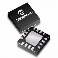
PIC16HV610-I/ML Microchip Technology, PIC16HV610-I/ML Datasheet - Page 9

PIC16HV610-I/ML
Manufacturer Part Number
PIC16HV610-I/ML
Description
1.75KB Flash, 64B RAM, 6 I/O, 8MHz Internal Oscillator 16 QFN 4x4mm TUBE
Manufacturer
Microchip Technology
Series
PIC® 16Fr
Datasheets
1.PIC12F609T-ISN.pdf
(26 pages)
2.PIC16F616T-ISL.pdf
(214 pages)
3.PIC16F616T-ISL.pdf
(8 pages)
4.PIC16HV616-ISL.pdf
(26 pages)
Specifications of PIC16HV610-I/ML
Core Processor
PIC
Core Size
8-Bit
Speed
20MHz
Peripherals
Brown-out Detect/Reset, POR, WDT
Number Of I /o
11
Program Memory Size
1.75KB (1K x 14)
Program Memory Type
FLASH
Ram Size
64 x 8
Voltage - Supply (vcc/vdd)
2 V ~ 5 V
Oscillator Type
Internal
Operating Temperature
-40°C ~ 85°C
Package / Case
16-QFN
Processor Series
PIC16H
Core
PIC
Data Bus Width
8 bit
Data Ram Size
64 B
Interface Type
RS-232 , USB
Maximum Clock Frequency
20 MHz
Number Of Programmable I/os
11
Number Of Timers
2
Maximum Operating Temperature
+ 85 C
Mounting Style
SMD/SMT
3rd Party Development Tools
52715-96, 52716-328, 52717-734
Development Tools By Supplier
PG164130, DV164035, DV244005, DV164005, PG164120, ICE2000
Minimum Operating Temperature
- 40 C
Height
0.88 mm
Length
4 mm
Supply Voltage (max)
5.5 V
Supply Voltage (min)
2 V
Width
4 mm
Lead Free Status / RoHS Status
Lead free / RoHS Compliant
For Use With
AC162083 - HEADER MPLAB ICD2 PIC16F616 8/14AC164324 - MODULE SKT FOR MPLAB 8DFN/16QFNXLT16QFN1 - SOCKET TRANSITION 14DIP TO 16QFN
Eeprom Size
-
Data Converters
-
Connectivity
-
Lead Free Status / Rohs Status
Details
4.1.4.1
The Load Configuration command is used to access
the Configuration Word (0x2007) and User ID (0x2000-
0x2003). This command sets the Program Counter
(PC) to address 0x2000 and loads the data latches with
one word of data.
To access the configuration memory, send the Load
Configuration command. Individual words within the
configuration memory can be accessed by sending
Increment Address commands and using load or read
data for program memory.
After the 6-bit command is input, ICSPCLK pin is
cycled an additional 16 times for the Start bit, 14 bits of
data and Stop bit (see Figure 4-4).
After the configuration memory is entered, the only way
to get back to the program memory is to exit the
Program/Verify mode by taking MCLR low (V
FIGURE 4-4:
4.1.4.2
After receiving this command, the chip will load in a
14-bit “data word” when 16 cycles are applied, as
described previously. A timing diagram of this
command is shown in Figure 4-5.
FIGURE 4-5:
2009 Microchip Technology Inc.
ICSPDAT
ICSPCLK
ICSPCLK
ICSPDAT
PIC12F609/12F615/16F610/16F616/PIC12HV609/12HV615/16HV610/16HV616
Load Configuration
Load Data for Program Memory
LOAD CONFIGURATION COMMAND
LOAD DATA FOR PROGRAM MEMORY COMMAND
1
1
0
0
2
2
0
0
1
T
SET
T
3
3
0
0
HLD
1
1
4
4
0
0
IL
).
5
X
5
X
T
T
DLY
6
DLY
6
X
X
T
T
1
DLY
DLY
1
3
2
1
1
strt_bit
strt_bit
2
2
LSb
LSb
T
3
T
3
SET
SET
T
T
HLD
HLD
1
1
1
1
4
4
5
5
DS41284D-page 9
15
15
MSb
MSb
16
16
stp_bit
stp_bit


