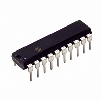
PIC16HV785-E/P Microchip Technology, PIC16HV785-E/P Datasheet - Page 39

PIC16HV785-E/P
Manufacturer Part Number
PIC16HV785-E/P
Description
3.5KB Flash, 128 RAM, 18 I/O 20 PDIP .300in TUBE
Manufacturer
Microchip Technology
Series
PIC® 16Fr
Datasheets
1.PIC16F616T-ISL.pdf
(8 pages)
2.PIC16F785-ISS.pdf
(206 pages)
3.PIC16F785-ISS.pdf
(10 pages)
4.PIC16F785-ISS.pdf
(28 pages)
Specifications of PIC16HV785-E/P
Core Processor
PIC
Core Size
8-Bit
Speed
20MHz
Peripherals
Brown-out Detect/Reset, POR, PWM, WDT
Number Of I /o
17
Program Memory Size
3.5KB (2K x 14)
Program Memory Type
FLASH
Eeprom Size
256 x 8
Ram Size
128 x 8
Voltage - Supply (vcc/vdd)
2 V ~ 5.5 V
Data Converters
A/D 14x10b
Oscillator Type
Internal
Operating Temperature
-40°C ~ 125°C
Package / Case
20-DIP (0.300", 7.62mm)
Processor Series
PIC16H
Core
PIC
Data Bus Width
8 bit
Data Ram Size
128 B
Interface Type
RS- 232, USB
Maximum Clock Frequency
32 MHz
Number Of Programmable I/os
18
Number Of Timers
3
Maximum Operating Temperature
+ 125 C
Mounting Style
Through Hole
3rd Party Development Tools
52715-96, 52716-328, 52717-734
Development Tools By Supplier
PG164130, DV164035, DV244005, DV164005, PG164120, ICE2000, DV164120, DM163029
Minimum Operating Temperature
- 40 C
On-chip Adc
10 bit, 14 Channel
Lead Free Status / RoHS Status
Lead free / RoHS Compliant
For Use With
AC162060 - HEADER INTRFC MPLAB ICD2 20PINAC164039 - MODULE SKT PROMATE II 20DIP/SOICACICE0203 - MPLABICE 20P 300 MIL ADAPTER
Connectivity
-
Lead Free Status / Rohs Status
Details
Available stocks
Company
Part Number
Manufacturer
Quantity
Price
Company:
Part Number:
PIC16HV785-E/P
Manufacturer:
MICROCHIP
Quantity:
12 000
4.2.2
Each of the PORTA pins is individually configurable as
an interrupt-on-change pin. Control bits IOCAx enable
or disable the interrupt function for each pin. Refer to
Register 4-4. The interrupt-on-change is disabled on a
Power-on Reset.
For enabled interrupt-on-change pins, the values are
compared with the old value latched on the last read of
PORTA. The ‘mismatch’ outputs of the last read are
OR’d together to set, the PORTA Change Interrupt flag
bit (RAIF) in the INTCON register (Register 2-3).
REGISTER 4-4:
© 2008 Microchip Technology Inc.
bit 7
Legend:
R = Readable bit
-n = Value at POR
bit 7-6
bit 5-0
Note 1: Global interrupt enable (GIE) must be enabled for individual interrupts to be recognized.
U-0
—
2: IOCA<5:4> always reads ‘1’ in XT, HS and LP OSC modes.
INTERRUPT-ON-CHANGE
Unimplemented: Read as ‘0’
IOCA<5:0>: Interrupt-on-change PORTA Control bits
1 = Interrupt-on-change enabled
0 = Interrupt-on-change disabled
U-0
—
IOCA: INTERRUPT-ON-CHANGE PORTA REGISTER
W = Writable bit
‘1’ = Bit is set
IOCA5
R/W-0
(2)
IOCA4
R/W-0
(2)
U = Unimplemented bit, read as ‘0’
‘0’ = Bit is cleared
IOCA3
R/W-0
This interrupt can wake the device from Sleep. The
user, in the Interrupt Service Routine, clears the inter-
rupt by:
a)
b)
A mismatch condition will continue to set flag bit RAIF.
Reading PORTA will end the mismatch condition and
allow flag bit RAIF to be cleared. The latch holding the
last read value is neither affected by an MCLR nor BOR
Reset. After these resets, the RAIF flag will continue to
be set if a mismatch is present.
Note:
Any read or write of PORTA. This will end the
mismatch condition, then,
Clear the flag bit RAIF.
(2)
PIC16F785/HV785
If a change on the I/O pin should occur
when the read operation is being executed
(start of the Q2 cycle), then the RAIF
interrupt flag may not get set.
IOCA2
R/W-0
x = Bit is unknown
IOCA1
R/W-0
DS41249E-page 37
IOCA0
R/W-0
bit 0


