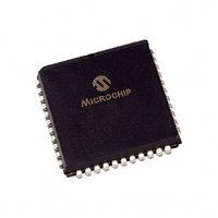
PIC16LC64A-04/L Microchip Technology, PIC16LC64A-04/L Datasheet - Page 68

PIC16LC64A-04/L
Manufacturer Part Number
PIC16LC64A-04/L
Description
IC,MICROCONTROLLER,8-BIT,PIC CPU,CMOS,LDCC,44PIN,PLASTIC
Manufacturer
Microchip Technology
Series
PIC® 16Cr
Specifications of PIC16LC64A-04/L
Rohs Compliant
YES
Core Processor
PIC
Core Size
8-Bit
Speed
4MHz
Connectivity
I²C, SPI
Peripherals
Brown-out Detect/Reset, POR, PWM, WDT
Number Of I /o
33
Program Memory Size
3.5KB (2K x 14)
Program Memory Type
OTP
Ram Size
128 x 8
Voltage - Supply (vcc/vdd)
2.5 V ~ 6 V
Oscillator Type
External
Operating Temperature
0°C ~ 70°C
Package / Case
44-PLCC
Package
44PLCC
Device Core
PIC
Family Name
PIC16
Maximum Speed
4 MHz
Operating Supply Voltage
3.3|5 V
Data Bus Width
8 Bit
Number Of Programmable I/os
33
Interface Type
I2C/SPI/USART
Number Of Timers
3
Processor Series
PIC16LC
Core
PIC
Data Ram Size
128 B
Maximum Clock Frequency
4 MHz
Maximum Operating Temperature
+ 70 C
Mounting Style
SMD/SMT
3rd Party Development Tools
52715-96, 52716-328, 52717-734
Development Tools By Supplier
ICE2000, DM163022
Minimum Operating Temperature
0 C
Lead Free Status / RoHS Status
Lead free / RoHS Compliant
Eeprom Size
-
Data Converters
-
Lead Free Status / Rohs Status
Details
Available stocks
Company
Part Number
Manufacturer
Quantity
Price
Company:
Part Number:
PIC16LC64A-04/L
Manufacturer:
Microchip Technology
Quantity:
10 000
- Current page: 68 of 337
- Download datasheet (3Mb)
PIC16C6X
7.3
An 8-bit counter is available as a prescaler for the
Timer0 module or as a postscaler for the Watchdog
Timer (WDT), respectively (Figure 7-6). For simplicity,
this counter is being referred to as “prescaler” through-
out this data sheet. Note that the prescaler may be
used by either the Timer0 module or the Watchdog
Timer, but not both. Thus, a prescaler assignment for
the Timer0 module means that there is no prescaler for
the Watchdog Timer, and vice-versa.
FIGURE 7-6:
DS30234D-page 68
Applicable Devices
61 62 62A R62 63 R63 64 64A R64 65 65A R65 66 67
RA4/T0CKI
CLKOUT (=Fosc/4)
WDT Enable bit
pin
Watchdog
Timer
Prescaler
Note: T0CS, T0SE, PSA, PS2:PS0 are (OPTION<5:0>).
BLOCK DIAGRAM OF THE TIMER0/WDT PRESCALER
T0SE
0
1
PSA
M
U
X
0
1
T0CS
M
U
X
0
8-bit Prescaler
8 - to - 1MUX
Time-out
8
M U X
WDT
1
0
1
PSA
M
U
X
The PSA and PS2:PS0 bits (OPTION<3:0>) determine
the prescaler assignment and prescale ratio.
When assigned to the Timer0 module, all instructions
writing to the TMR0 register (e.g. CLRF
MOVWF TMR0, BSF TMR0,bitx) will clear the pres-
caler count. When assigned to the Watchdog Timer, a
CLRWDT instruction will clear the Watchdog Timer and
the prescaler count. The prescaler is not readable or
writable.
Note:
PSA
PS2:PS0
Cycles
SYNC
Writing to TMR0 when the prescaler is
assigned to Timer0 will clear the prescaler
count, but will not change the prescaler
assignment.
2
1997 Microchip Technology Inc.
TMR0 reg
Data Bus
8
Set flag bit T0IF
on Overflow
TMR0,
Related parts for PIC16LC64A-04/L
Image
Part Number
Description
Manufacturer
Datasheet
Request
R

Part Number:
Description:
Manufacturer:
Microchip Technology Inc.
Datasheet:

Part Number:
Description:
Manufacturer:
Microchip Technology Inc.
Datasheet:

Part Number:
Description:
Manufacturer:
Microchip Technology Inc.
Datasheet:

Part Number:
Description:
Manufacturer:
Microchip Technology Inc.
Datasheet:

Part Number:
Description:
Manufacturer:
Microchip Technology Inc.
Datasheet:

Part Number:
Description:
Manufacturer:
Microchip Technology Inc.
Datasheet:

Part Number:
Description:
Manufacturer:
Microchip Technology Inc.
Datasheet:

Part Number:
Description:
Manufacturer:
Microchip Technology Inc.
Datasheet:


