C25BNF230B EATON CUTLER HAMMER, C25BNF230B Datasheet - Page 15
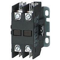
C25BNF230B
Manufacturer Part Number
C25BNF230B
Description
Definite Purpose Contactor
Manufacturer
EATON CUTLER HAMMER
Datasheet
1.C25FNF375A.pdf
(54 pages)
Specifications of C25BNF230B
Load Current Inductive
30A
Load Current Resistive
40A
No. Of Poles
2
Contact Configuration
DPST-NO
Relay Mounting
Panel
Coil Voltage Vac Nom
240V
Contact Voltage Ac Nom
600V
Horsepower
5hp


October 2008
Contents
Description
Starters 15 – 45A
Product Description
Cutler-Hammer
Purpose Starters from Eaton’s electrical
business combine the features and
flexibility of the C25 Definite Purpose
Contactors and XT Series Bi-metallic
Ambient Compensated Overload
Relays.
CA08102001E
Product Description . . . . . . 35-15
Features . . . . . . . . . . . . . . . 35-15
Standards and
Technical Data
Product Selection . . . . . . . . 35-16
Overload Relay
Dimensions. . . . . . . . . . . . . 35-30
Renewal Parts. . . . . . . . . . . 35-32
Certifications . . . . . . . . . . 35-15
and Specifications . . . . . . 35-15
Specifications . . . . . . . . . 35-18
A27 Starter
®
A27 and B27 Definite
Page
Features
Standards and Certifications
Technical Data and
Specifications
Table 35-40. Terminal Wire Sizes
Table 35-41. Power Terminals — Load — Cu
Only (Stranded or Solid)
Control Terminals — Cu Only
Line Side (Contactor)
Terminal
Type
Screw/
Pressure Plate
Box Lug —
15 – 45A
Terminal Range
15 and 25
Ampere
30, 40
and 45
Ampere
12 – 16 AWG stranded, 12 – 14 AWG solid
For more information visit: www.eaton.com
Line side (contactor) torque ratings can be
found on Page 35-5.
Selectable Manual or Automatic
Reset operation
Class 10 Trip Class
Bimetallic, ambient compensated
operated. Trip free mechanism.
Electrically isolated NO-NC contacts
(pull TEST button to test)
Shrouded or fingerproof terminals
to reduce possibility of electrical
shock
Single-phase sensitivity
UL Recognized Components
UL File #E-1491, Guide NLDX2
CSA Certified Components
File #LR353, Guide 380W-1.14
Class 3211 04
Definite Purpose Contactors & Starters
Starters
15 – 45A, Single and Three-Phase — A27, B27
14 – 8 AWG
14 – 2 AWG
Wire Range — Solid or
Stranded
Power
Terminals
8 – 14 AWG
4 – 14 AWG
Torque Rating
16 lb-in (14 – 8 AWG)
31 lb-in (14 – 2 AWG)
Coil Terminals
12 – 16 AWG
12 – 16 AWG
Figure 35-7. Starter Wiring Diagrams
1
2/T1
1
L1
T1
2/T1 4/T2
L1
T1
AC Motor
AC Motor
L2
L2
T2
Single-Phase
Connections
4/T2
Three-Phase
Connections
T2
6/T3
L3
T3
(Supplied
Common
Wire “C”
Control)
(Supplied
Common
Wire “C”
Control)
98
97
96
95
with
13
14
98
97
96
95
with
13
14
1NO Aux.
Supplied)
(Supplied
1NO Aux.
1NO Aux.
Supplied)
(Supplied
1NO Aux.
Wire “D”
Wire “D”
Contact)
Contact)
Contact
Contact
(When
(When
Reset
with
with
35-15
35
Related parts for C25BNF230B
Image
Part Number
Description
Manufacturer
Datasheet
Request
R

Part Number:
Description:
PROGRAMMABLE LOGIC CONTROLLER
Manufacturer:
EATON CUTLER HAMMER
Part Number:
Description:
Pm Power Pro 3000/5000 A-B Accel/On Interface
Manufacturer:
EATON CUTLER HAMMER
Part Number:
Description:
Handle Tie Bar For (2) - 1 Pole Type BR Breakers
Manufacturer:
EATON CUTLER HAMMER
Part Number:
Description:
Type CH Breaker 150A/2 Pole 120/240V 10K
Manufacturer:
EATON CUTLER HAMMER
Part Number:
Description:
Tenant Branch Breaker 125A/3 Pole 120/240V 42K
Manufacturer:
EATON CUTLER HAMMER
Part Number:
Description:
Type CL Breaker 25A/1Pole 120/240V 10K-Classified 1" Ckt Bkr
Manufacturer:
EATON CUTLER HAMMER
Part Number:
Description:
FD BREAKER 1P 80 AMP WITH LOAD ONLY TERMINALS
Manufacturer:
EATON CUTLER HAMMER
Part Number:
Description:
GD 2 POLE BREAKER, 25 AMP, SINGLE PACKED
Manufacturer:
EATON CUTLER HAMMER
Part Number:
Description:
Handle Tie Bar For (2) - 1 Pole Type BR Breakers
Manufacturer:
EATON CUTLER HAMMER
Part Number:
Description:
Type CL Breaker 25A/1Pole 120/240V 10K-Classified 1" Ckt Bkr
Manufacturer:
EATON CUTLER HAMMER