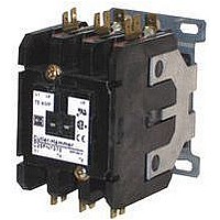
C25FNF360B EATON CUTLER HAMMER, C25FNF360B Datasheet - Page 20

C25FNF360B
Manufacturer Part Number
C25FNF360B
Description
Definite Purpose Contactor
Manufacturer
EATON CUTLER HAMMER
Datasheet
1.C25FNF375A.pdf
(54 pages)
Specifications of C25FNF360B
Load Current Inductive
60A
Load Current Resistive
75A
No. Of Poles
3
Contact Configuration
3PST-NO
Relay Mounting
Panel
Coil Voltage Vac Nom
240V
Nom Operating Power
15kW
Contact Voltage Ac Nom
600V
Operating Voltage
600VAC
Switching Power Ac1
7.5kW
Switching Power Ac3
15kW
Switching Current Ac1
75A
Switching Current Ac3
60A
Rohs Compliant
Yes
Supply Voltage
230V
Contactor Direction
Non Reversing
Lead Free Status / RoHS Status
Contains lead / RoHS non-compliant
35
35-20
Contents
Description
Starters 15 – 75A
Product Description
Cutler-Hammer
Purpose Starters from Eaton’s electrical
business combine the features and
flexibility of the C25 Definite Purpose
Contactors and C396 Electronic Over-
load Relays.
Product Description . . . . . . . 35-20
Features . . . . . . . . . . . . . . . . 35-20
Standards and
Catalog Number
Product Selection . . . . . . . . 35-22
Overload Relay
Stand-Alone
Definite Purpose Contactors & Starters
Starters
15 – 75A, Single and Three-Phase — A29, B29
Certifications . . . . . . . . . . . 35-20
Selection . . . . . . . . . . . . . . 35-21
Specifications . . . . . . . . . . 35-24
Overload Relay . . . . . . . . . 35-25
A29 Starter
®
A29 and B29 Definite
Page
Features
Standards and Certifications
For more information visit: www.eaton.com
Standard Version: Selectable Trip
Class (5, 10, 20, 30) with Selectable
Manual or Auto Reset (45 and
65 mm Frames)
Current Adjustment Range: 5:1
Self-Powered Design — will accept
AC voltages from 12 to 690V
50/60 Hz
Ambient Temperature Compensation
Low Heat Generation
Phase Loss Protection
Phase Unbalance Protection
Electrically isolated 1NO-1NC
Contacts (Push-to-Test)
Trip Status Indicator
UL Listed Components
CSA Certified Components
IEC EN 60947-4-1, EN 60947-5-1
CE Certified Components
CCC Certified Components
RoHS Certified Components
Figure 35-9. Starter Wiring Diagrams
1
2/T1
1
L1
T1
2/T1 4/T2
L1
T1
AC Motor
AC Motor
L2
L2
T2
Single-Phase
Connections
4/T2
Three-Phase
Connections
T2
6/T3
L3
T3
(Supplied
Common
Wire “C”
Control)
(Supplied
Common
Wire “C”
Control)
98
97
96
95
with
13
14
98
97
96
95
with
13
14
1NO Aux.
Supplied)
(Supplied
1NO Aux.
1NO Aux.
Supplied)
(Supplied
1NO Aux.
Wire “D”
Wire “D”
Contact)
Contact)
Contact
Contact
(When
(When
Reset
with
with
CA08102001E
October 2008


