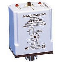
ARP024A6R MACROMATIC CONTROLS, ARP024A6R Datasheet - Page 4

ARP024A6R
Manufacturer Part Number
ARP024A6R
Description
ALTERNATING LOAD RELAY, SPDT, 10A
Manufacturer
MACROMATIC CONTROLS
Datasheet
1.ARP024A6R.pdf
(4 pages)
Specifications of ARP024A6R
Contact Current Max
10A
Contact Voltage Ac Nom
240V
Contact Voltage Dc Nom
30V
Contact Configuration
SPDT
Relay Mounting
Plug In
Average Power Consumption
3VA
External Height
79mm
Lead Free Status / RoHS Status
Lead free / RoHS Compliant
Application Data
Voltage Tolerances: +10%/-15% of control voltage at 50/60Hz.
Load (Burden): Less than 3VA
Output Contacts:
10A @ 240V AC/30V DC,
1/2HP @ 120/240V AC (N.O.), 1/3HP @ 120/240VAC (N.C.)
Life:
Mechanical: 10,000,000 operations
Full Load: 100,000 operations
Temperature: -28
Dimensions
Typical Installations
In the initial off state (diagram below left), both the LEAD Control
Switch and the LAG Control Switch are open, the Alternating
Relay is in the LOAD A position, and both loads are off. The red
LED marked “LOAD A” is ON. When the LEAD Control Switch
closes, it energizes Load M1. As long as the LEAD Control
Switch remains closed, Load M1 remains energized. If the LAG
Control Switch closes, it energizes Load M2. When the LAG
Control Switch opens, Load M2 is turned off. When the LEAD
Control Switch opens, Load M1 is turned off and the Alternating
Relay toggles to the LOAD B position. The red LED marked
“LOAD B” is ON. When the LEAD Control Switch closes, it turns
on Load M2. If the LAG Control Switch closes, it will energize
Load M1. When the LAG Control Switch opens, Load M1 is
turned off. When the LEAD Control Switch opens, Load M2 is
turned off, the Alternating Relay toggles back to the LOAD A
position, and the process can be repeated again.
1/10
o
to 65
Figure A
2.4 (60)
o
C (-20
o
to 150
o
(43)
F)
1.7
The diagram below right illustrates a type of operation known as “Sequence
On - Simultaneously Off (S.O.S.O.)”-the two loads are energized sequentially,
but remain on together until the OFF switch is opened.
In the initial OFF state, all three switches are open, the Alternating Relay is in
the LOAD A position, and both loads are off. No action happens with the
Alternating Relay or either load when the OFF Switch closes. When the
LEAD Switch closes, Load M1 turns on. When the LAG Switch closes, Load
M2 turns on. Both loads remain on as long as all three switches are closed.
When the LAG Switch opens, Load M2 remains on because the OFF Switch
is still closed. When the LEAD Switch opens, Load M1 remains on because
the STOP Switch is still closed. When the OFF Switch opens, both Load M1
and Load M2 are turned off simultaneously. The Alternating Relay toggles to
the LOAD B position. The entire cycle is then repeated, but with Load M2
energized first followed by Load M1.
ALTERNATING RELAYS
File #E109466
Transient Protection: 10,000 volts for 20 microseconds
Indicator LED's: 2 LED's marked LOAD A and LOAD B
Optional Selector Switch Settings:
LOCK LOAD A (always energizes first)
ALTERNATE
LOCK LOAD B (always energizes first)
Approvals:
(74)
2.9
File #LR45565
(79)
3.1
Application Data & Dimensions
EN60947-1, EN60947-5-1
DPDT Cross-Wired
Figure B
EMC Directives
Low Voltage &
Inches (Millimeters)
All Dimensions in
File #E109466
appropriate
socket
with
45


