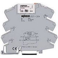
857-303 WAGO, 857-303 Datasheet - Page 6

857-303
Manufacturer Part Number
857-303
Description
POWER RELAY, 1CO, 12VDC, 5A, DIN RAIL
Manufacturer
WAGO
Datasheet
1.857-303.pdf
(12 pages)
Specifications of 857-303
Relay Type
Miniature
Coil Voltage Vdc Nom
12V
Contact Current Max
6A
Contact Voltage Ac Nom
250V
Contact Configuration
SPCO
Coil Type
DC
Coil Current
17mA
Nom Operating Power
700mW
Rohs Compliant
Yes
Signal Conditioners
Item no.
Configuration
Input signal
Sensor connection
Measuring range
Cold junction compensation
Output signal
Output signal (can be inverted)
Load impedance
Step response
Supply voltage U
Additional configuration options for 857-801/857-811 Series via configuration software
• Selection of additional sensor types
• Inversion of output signal
• Adjustable step response
Module width:
Test voltage:
Transmission error:
Supply Voltage:
Temperature range:
Approvals:
*pending
Jumpers for 857 Series Signal Conditioning and Relay Module
Jumper Comb, Insulated White, 18A
2 Pole
3 Pole
4 Pole
5 Pole
6 Pole
7 Pole
8 Pole
9 Pole
10 Pole
Red insulated part number adder
Blue insulated part number adder
Example, Blue insulated 2 pole
Technical Data for Signal Conditioners
<______________ 94 mm/3.68 in ______________>
N
6.0 mm/0.236 in
2.5 kV AC / 50 Hz / 1 min
< 0.1 % of full scale value
16.8 V ... 31.2 V
-25 °C ... +70 °C
1, r , g*
Class 1 Div. 2
Groups A, B, C, D
______________
2- and 4-wire: 180ms
LISTED
Signal Conditioner
3-wire: 360ms
DIP switch
857-800
for RTDs
1
2
3
4
IN
–
Pt 100, Pt 200, Pt 500, Pt 1000
0 (2) … 10mA; 0 (4) … 20mA
OUT
POWER
0 (1) … 5V, 0 (2) … 10V,
0 …1 kΩ, 0 … 4.5 kΩ
2-wire, 3-wire, 4-wire
-200°C … +850°C
5
6
7
8
≤ 600 Ω (I-output)
≥ 2 kΩ (U-output)
OUT+
GND 1
Us+
GND 2
24VDC
Part Number
859-402
859-403
859-404
859-405
859-406
859-407
859-408
859-409
859-410
.../000-005
.../000-006
859-402/000-006
–
via configuration software
2- and 4-wire: 60ms ... 3s
configuration software
3-wire: 120ms ... 6s
Signal Conditioner
DIP switch or
857-801
for RTDs
1
2
3
4
IN
OUT
POWER
5
6
7
8
Item no.
Configuration
Input signal
(switchable in a calibrated way)
Output signal
(switchable in a calibrated way)
Load impedance
Max. operating frequency
Supply voltage U
OUT+
GND 1
Us+
GND 2
Cold junction on: 120ms
Cold junction off: 60ms
TC+
TC–
Signal Conditioner
for Thermocouples
N
1
2
3
4
DIP switch
857-810
IN
–
Configuration software
- FDT frame application
- DTM (Device Tool Manager)
WAGO USB service cable
OUT
POWER
Type K: -150°C … +1350°C
0 (2) … 10mA; 0 (4) … 20mA
Type J: -150°C … +1200°C
Isolation Amplifier, Configurable
GND 1
GND 3
Thermocouple of type J, K
0 (1) … 5V, 0 (2) … 10V,
with Zero/Span Adjustment
IN+
Us+
(switchable via DIP switch)
5
6
7
8
on/off (default: on)
0 (1) … 5V, 0 (2) … 10V,
0 (1) … 5V, 0 (2) … 10V,
≤ 600 Ω (I-output)
≥ 2 kΩ (U-output)
OUT+
GND 1
Us+
GND 2
≤ 600 Ω (I-output)
≥ 2 kΩ (U-output)
100Hz / > 5kHz
1
2
3
4
0 (4) … 20mA,
0 (4) … 20mA,
24VDC
DIP switch
IN
857-400
24VDC
POWER
Cold junction on: 120ms ... 6s
Cold junction off: 60ms ... 3s
OUT
via configuration software
configuration software
TC+
TC–
Signal Conditioner
for Thermocouples
5
6
7
8
DIP switch or
1
2
3
4
OUT+
GND 2
Us+
GND 3
857-811
IN
759-370
759-380
750-923
OUT
POWER
0 … +30 V (31.2V U
Isolation Amplifier, Confi
GND 1
GND 3
0 (2) … 10mA, 0 (4) …
-10 … +10V, -20 … +
IN+
5
6
7
8
DO
0 (1) … 5V, 0 (2) …
configuration softw
OUT+
GND 1
Us+
GND 2
with Digital Outp
≤ 600 Ω (I-outpu
≥ 2 kΩ (U-output
1
2
3
4
DIP switch or
IN
U,I
DO
857-401
24VDC
–
POWER
OUT
U,I
IN
;1
5
6
7
8


