S2-12VDC PANASONIC EW, S2-12VDC Datasheet - Page 3
S2-12VDC
Manufacturer Part Number
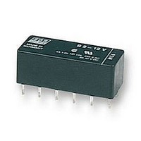
S2-12VDC
Description
POWER RELAY DPST-NO/NC 12VDC 4A PC BOARD
Manufacturer
PANASONIC EW
Datasheet
1.S2-12VDC.pdf
(5 pages)
Specifications of S2-12VDC
Relay Type
PCB
Coil Voltage Vdc Nom
12V
Contact Current Max
4A
Contact Voltage Ac Nom
250V
Contact Voltage Dc Nom
30V
Coil Resistance
720ohm
Contact Configuration
DPST-NC / DPST-NO
Lead Free Status / RoHS Status
Lead free / RoHS Compliant


Schematic
Single side stable
Deenergized position
2 coil latching
Diagram shows the “reset”
position when terminals 6
and 7 are energized.
Energize terminals 1 and
12 to transfer contacts.
REFERENCE DATA
1. Maximum switching power
4.-(1) Coil temperature rise
Tested Sample: S4-24V, 4 Form A
6. Influence of adjacent mounting
en_ds_61105_0000: 130804D
1,000
100
100
(1)
10
90
80
70
60
50
40
30
20
10
–30
0
+30
0
(2)
Single side stable
0.2
DC resistive load
(3)
0.1
Drop-out voltage
Pick-up voltage
0.4
Coil operating power, W
(1) & (3) relays
are energized
(Bottom view)
Inter-relay distance, mm
Contact current, A
0.6
5
0.8
AC resistive load
1
2a2b
2a2b
Note: When installing an S-relay near another, and there is no effect
1.0
4A
0A
Set
from an external magnetic field, be sure to leave at least 10 mm
.394 inch
listed in the catalog.
10
1.2
12
12
1
1
10
-
+
+
-
11
11
2
2
between relays in order to achieve the performance
10
2. Life curve
4.-(2) Coil temperature rise
Tested Sample: S4-24V, 4 Form A
10
3
3
–30
+30
0
2 coil latching
4
9
4
9
1,000
100
500
100
50
30
10
90
80
70
60
50
40
30
20
10
0
0
5
8
5
8
Coil operating
power, 0.2 W
6
7
6
7
1
Pick-up voltage
1
Inter-relay distance, mm
Reset
-
+
5
2
2
3a1b
3a1b
Contact current, A
Contact current, A
3
3
Set
125 V AC
(cos = 1.0)
250 V AC
(cos = 1.0)
4
4
12
12
1
1
-
-
+
+
10
11
11
5
2
5
2
10
10
3
3
6
4
9
4
9
5
8
5
8
3. Contact reliability
Condition: 1V DC, 1mA
Detection level 10 Ω
Tasted Sample: S4-24V, 10pcs
5. Operate and release time
(Single side stable type)
Tested Sample: S4-24V, 10pcs
7. Thermal electromotive force
6
7
6
7
Reset
-
+
99.9
99.0
95.0
70.0
50.0
30.0
10.0
200
100
5.0
2.0
1.0
0.5
0.2
0.1
20
18
16
14
12
10
8
6
4
2
0
Max.
Min.
4a
4a
80
Release time
Set
2
12
12
1
1
Release time (with diode)
+
-
-
+
4
100
No. of operations, 10
Coil applied voltage, %V
11
m = 1.6
95% reliability limit:
14.6 million times
(weibul probability paper)
11
2
2
: 79 million time
: 51 million time
1.0
NR-H
6
Minute
10
10
Operate time
3
3
120
NF relay S relay
8
4
9
4
9
10
5
8
5
8
140
7
Max.
Min.
Max.
Min.
10.0
6
7
6
7
12
+
Reset
-
S
3
Related parts for S2-12VDC
Image
Part Number
Description
Manufacturer
Datasheet
Request
R

Part Number:
Description:
RELAY, PCB, DPNO & DPNC
Manufacturer:
PANASONIC EW
Datasheet:

Part Number:
Description:
POWER RELAY DPST-NO/NC 24VDC 4A PC BOARD
Manufacturer:
PANASONIC EW
Datasheet:
Part Number:
Description:
POWER RELAY DPST-NO/NC 24VDC 4A PC BOARD
Manufacturer:
PANASONIC EW
Datasheet:
Part Number:
Description:
RELAY, PCB, DPNO & DPNC
Manufacturer:
PANASONIC EW
Datasheet:
Part Number:
Description:
RELAY, PCB, DPNO & DPNC
Manufacturer:
PANASONIC EW
Datasheet:

Part Number:
Description:
POWER RELAY, 24VDC, 30A, SPST-NO
Manufacturer:
PANASONIC EW
Datasheet:

Part Number:
Description:
POWER RELAY, SPDT, 12VDC, 10A, PC BOARD
Manufacturer:
PANASONIC EW

Part Number:
Description:
POWER RELAY, 24VDC, 5A, SPST-NO, PCB
Manufacturer:
PANASONIC EW
Datasheet:


Part Number:
Description:
SIGNAL RELAY, DPDT, 4.5VDC, 1A, SMD
Manufacturer:
PANASONIC EW
Datasheet:

Part Number:
Description:
SIGNAL RELAY, DPDT, 5VDC, 2A, PC BOARD
Manufacturer:
PANASONIC EW
Datasheet:


Part Number:
Description:
PHOTOMOS RELAY, 60VDC, 400mA
Manufacturer:
PANASONIC EW
Datasheet:

Part Number:
Description:
PHOTOMOS RELAY, 400V, 150mA
Manufacturer:
PANASONIC EW
Datasheet: