55.14.9.024.0000 FINDER, 55.14.9.024.0000 Datasheet
55.14.9.024.0000
Specifications of 55.14.9.024.0000


Related parts for 55.14.9.024.0000


55.14.9.024.0000 Summary of contents
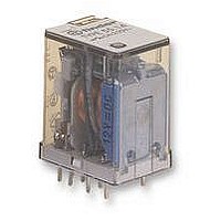
Page 1
... Single phase motor rating (230 V AC) kW Breaking capacity DC1: 30/110/220V Minimum switching load mW (V/mA) Standard contact material Coil specification Nominal voltage ( (50/60 Hz Rated power AC/DC VA (50 Hz)/W Operating range AC DC Holding voltage AC/DC Must drop-out voltage AC/DC Technical data Mechanical life AC/DC cycles ...
Page 2
... Single phase motor rating (230 V AC) kW Breaking capacity DC1: 30/110/220 V Minimum switching load mW (V/mA) Standard contact material Coil specification Nominal voltage ( (50/60 Hz Rated power AC/DC VA (50 Hz)/W Operating range AC DC Holding voltage AC/DC Must drop-out voltage AC/DC Technical data Mechanical life AC/DC cycles ...
Page 3
... The dual-purpose Finder test button can be used in two ways: Case 1) The plastic pip (located directly above the test button) remains intact. In this case, when the test button is pushed, the contacts operate. When the test button is released the contacts return to their former state ...
Page 4
... Burst (5...50)ns, 5 kHz Surge (1.2/50 µ (differential mode) Other data Bounce time: NO/NC Vibration resistance (5…55)Hz: NO/NC Shock resistance Power lost to the environment without contact current with rated current Recommended distance between relays mounted on PCB Contact specification Electrical life (AC) v contact current 2 and 3 pole relays Resistive load - cosϕ ...
Page 5
... Rear flange mount adaptor for 55.32, 55.33, 55.34 056.26 056.26 with relay Top 35 mm rail (EN 60715) adaptor for 55.32, 55.33, 55.34 056.27 056.27 with relay 55 Series - General purpose relays coil data Resistance Rated coil Nominal Coil consumption voltage ...
Page 6
... Module Socket — 94.32 — 94.33 94.34 — 94.34 See page Series - Socket overview for 55 series relays Relay Description 55.32 Screw terminal (Box clamp) socket 55.33 - Top terminals - Contacts 55.32 - Bottom terminals - Coil 55.34 Relay Description 55.34 - For fast cable connections ...
Page 7
... LED + Varistor LED + Varistor LED + Varistor RC circuit RC circuit DC Modules with non-standard polarity RC circuit (+A2) on request. Residual current by-pass 94 Series - Sockets and accessories for 55 series relays 94.02 Blue 55.32 094.91.3 094.91.30 094.91.3 094.91.30 094.91.3 094.91.30 094. 250 °C –40…+70 Nm 0.5 ...
Page 8
... LED + Varistor housing are LED + Varistor available on request. RC circuit Green LED is standard. RC circuit Red LED available RC circuit on request. Residual current by-pass 8 94 Series - Sockets and accessories for 55 series relays 94.54.1 (blue) 55.32, 55. 250 °C –25…+ solid wire mm 2 2x(0.2…1.5) AWG 2x(24… ...
Page 9
... Modules in Black LED + Varistor housing are LED + Varistor available on request. RC circuit Green LED is standard. RC circuit Red LED available on RC circuit request. Residual current by-pass 94 Series - Sockets and accessories for 55 series relays 94.72 Blue 55.32 55. 250 °C –40…+ (94.72/73/74) solid wire ...
Page 10
... Rated values Dielectric strength Protection category 094.91.3 Ambient temperature Screw torque Wire strip length Max. wire size for 94.82.3, 94.84.3 and 94.84.2 sockets 060. Series - Sockets and accessories for 55 series relays 94.82.3 Blue 55.32 094.91.3 094.06 94.84.2 Blue 55.32, 55.34 094.91.3 094.06 ...
Page 11
... LED + Varistor available on request. RC circuit RC circuit Green LED is standard. RC circuit Red LED available on request. Residual current by-pass 94 Series - Sockets and accessories for 55 series relays 94.92.3 (blue) 94.92.30 (black) 94.94.3 (blue) 94.94.30 (black) 55.32 094.91.3 094. 250 °C –25…+70 Nm 0.5 ...
Page 12
... For relay type Accessories 94.22 Metal retaining clip (supplied with socket - packaging code SMA) Approvals Technical data (according to type): Rated values Dielectric strength Ambient temperature 12 94 Series - Sockets and accessories for 55 series relays 94.12 Blue 55. 250 °C –40…+70 94.12 94.13 94.22 Blue 55 ...
Page 13
... Ambient temperature Packaging codes How to code and identify retaining clip and packaging options for sockets. Example Series - Sockets and accessories for 55 series relays 94.32 Blue 55. 250 °C –40…+ Standard packaging SM Metal retaining clip SP Plastic retaining clip Without retaining clip 94.32.0 94.33 94 ...
Page 14
...