60.43.9.012.0000 FINDER, 60.43.9.012.0000 Datasheet
60.43.9.012.0000
Specifications of 60.43.9.012.0000


Related parts for 60.43.9.012.0000


60.43.9.012.0000 Summary of contents
Page 1
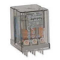
... AgNi 110 - 120 - 230 - 240 - 400 110 -125 - 220 2.2/1.3 (0.8…1.1 (0.8…1.1)U N 0 0 · /50 · 200 · 9/9 3.6 1,000 °C –40…+ 60.13 3 pole - 10 A power contacts • 11 pin plug-in • 32.5 36 (3PDT) 10/20 250/400 ...
Page 2
... Breaking capacity DC1: 30/110/220 V Minimum switching load mW (V/mA) Standard contact material Coil specification Nominal voltage ( (50/60 Hz) N Rated power AC/DC VA (50 Hz)/W Operating range Holding voltage Must drop-out voltage Technical data Mechanical life AC/DC Electrical life at rated load AC1 Operate/release time Insulation between coil and contacts (1.2/50 µ ...
Page 3
... N DC (0.8…1.1)U N 0 0 · /50 · 200 · 9/9 3.6 1,000 °C –40…+ 60.63 3 pole - 10 A power contacts • Flange mount/Faston 187 • 32.2 36.5 3.6 7 5.9 6.2 4 (3PDT) 10/20 250/400 2,500 500 0.37 10/0 ...
Page 4
... A2 Lockable test button and mechanical flag indicator (0040) The dual-purpose Finder test button can be used in two ways: Case 1) The plastic pip (located directly above the test button) remains intact. In this case, when the test button is pushed, the contacts operate. When the test button is released the contacts return to their former state ...
Page 5
... Conducted disturbance immunity Burst (5...50)ns, 5 kHz Surge (1.2/50 µ (differential mode) Other data Bounce time: NO/NC Vibration resistance (5…55)Hz, max. ± 1 mm: NO/NC Shock resistance Power lost to the environment Contact specification Electrical life (AC) v contact current 7 10 Resistive load - cosϕ Inductive load - cosϕ ...
Page 6
... Current sensing AC coil data to be energised, Coil code 4251 4181 4161 4121 4101 4051 4041 4031 4021 4011 Other types of current sensing relays are available on request - (A) (A) ( min N max 1.7 2.0 2.4 1.5 1 ...
Page 7
... Example series P.C.B.relay (3PDT) with coil rated No. of poles Series (DPDT (3PDT) Type 4 = P.C. Coil version = Series General Purpose Relays 10 A ORDERING INFORMATION Coil version diode in parallel to coil (positive to pin (50/60 Hz Coil voltage 006 = 6 V 012 = 12 V 024 = 24 V 048 = 48 V 060 = 60 V 110 = 110 V ...
Page 8
... Series General Purpose Relays 10 A DIELECTRIC STRENGTH tested at leakage current ≤ for 1 min SURGE TEST (1.2/50 µs) BETWEEN COIL AND CONTACTS ISOLATION RESISTANCE ISOLATION GROUP MAXIMUM SWITCHING FREQUENCY 60.43 AMBIENT TEMPERATURE MECHANICAL LIFE RINA C PROTECTION CATEGORY OF ENCLOSURES OPERATE AND RELEASE TIME ...
Page 9
... Contact life vs AC1 load at 1800 cycles/ 0.8 k 0.6 0.4 1 0.8 0.6 0.4 COS Load reduction factor vs cos 60 Series General Purpose Relays 10 A 2.5 3 Breaking capacity for DC1 load at 1800 cycles/ load applied to 1 contact B = load applied to 2 contacts in series C = load applied to 3 contacts in series 0 ...
Page 10
... VERSIONS alternating current 50/ direct current AM - current sensing coil with a diode in parallel RATED POWER OPERATING RANGE HOLDING VOLTAGE MUST DROP-OUT VOLTAGE NOMINAL MAGNETOMOTIVE FORCE THERMAL INSULATION CLASS OF WIRE THERMAL RESISTANCE CONDUCTED DISTURBANCE IMMUNITY AC VERSION DATA R values relate to +20°C. Tolerance of R and I values: ± 10%. ...
Page 11
... DC coil min pick-up voltage vs ambient temperature. Umin = pick-up voltage U = rated voltage HEATING TIME (min) Temperature rise "∆t " vs applied voltage coils. 60 Series General Purpose Relays 10 A COIL SPECIFICATIONS Temperature rise "∆t " vs applied voltage. DC coils Temperature rise "∆t " vs applied voltage coils. ...