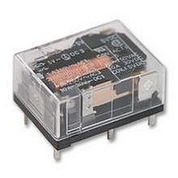
G6CK-1117P-US 5DC Omron, G6CK-1117P-US 5DC Datasheet

G6CK-1117P-US 5DC
Specifications of G6CK-1117P-US 5DC
Related parts for G6CK-1117P-US 5DC
G6CK-1117P-US 5DC Summary of contents
Page 1
... Contact Type 1: Standard 4. Enclosure Ratings 4: Fully sealed 6. Approved Standards 7: Flux protection 7. Rated Coil Voltage G6C VDE Self-clinching PCB Flux protection Fully sealed G6C-1117C-US G6C-1114C-US G6C-2117C-US G6C-2114C-US G6CU-1117C-US G6CU-1114C-US G6CU-2117C-US G6CU-2114C-US G6CK-1117C-US G6CK-1114C-US G6CK-2117C-US G6CK-2114C-US P: Straight PCB C: Self-clinching PCB US: UL/CSA certified 12, 24 VDC ...
Page 2
... Back Connecting Sockets Applicable relay G6C(U)-1114P-US G6C(U)-1117P-US G6C(U)-2114P-US G6C(U)-2117P-US G6CK-1114P-US G6CK-1117P-US G6CK-2114P-US G6CK-2117P-US *Not applicable to the self-clinching versions. The operating current for the socket max. Removal Tool P6B-Y1 Hold-down Clips P6B-C2 Specifications Coil Ratings ■ Single-side Stable Type ...
Page 3
... Contact material Ag Alloy (Cd free) Rated carry current 10 A Max. switching voltage 380 VAC, 125 VDC (the case of latching 250 VAC, 125 VDC) Max. switching current 10 A Max. switching power 2,500 VA, 300 W Failure rate (reference value VDC –6 P level: λ 0 Note: operations Characteristics ■ ...
Page 4
G6C Approved Standards ■ UL508 (File No. E41643) Model Contact form G6C-1114P-US SPST-NO G6C-1114C-US G6C-1117P-US G6C-1117C-US G6C-2114P-US SPST-NO + SPST-NC G6C-2114C–US G6C-2117P-US G6C-2117C-US CSA C22.2 No.14 (File No. LR31928) Model Contact form G6C-1114P-US SPST-NO G6C-1114C-US G6C-1117P-US G6C-1117C-US G6C-2114P-US SPST-NO + ...
Page 5
... SPST-NO + SPST-NC AC inductive load AC resistive load (cosφ = 0.4) DC inductive load (L ms) DC resistive load Switching voltage (V) mum value in a varying range of operating power voltage, not a continuous voltage. G6C Endurance G6C-2114P-US 250-VAC resistive 30-VDC resistive G6C-1114P-US 250-VAC resistive 30-VDC resistive G6C-2114P-US G6C-1114P-US ...
Page 6
G6C Dimensions Note: 1. All units are in millimeters unless otherwise indicated. 2. Orientation mark is indicated as follows: G6C-@117P-US 20 max. (19.9)* 0.6 0.8 10.16 7.62 G6C-@117C-US 20 max. (19.9)* 3.2 0.6 0.8 10.16 7.62 G6C-@114P-US 20 max. (19.9)* ...
Page 7
G6C G6CU-@117P-US 20 max. (19.9)* 0.6 10.16 G6CU-@117C-US 20 max. (19.9)* 3.2 0.6 10.16 G6CU-@114P-US G6CU-@114C-US 20 max. (19.9)* 3.2 0.6 10.16 202 15 max. (14.9)* 10 max. (9.9)* 3.5 0.3 0.8 0.4 0.8 1.11 7.62 10.16 *Average value 15 ...
Page 8
... G6C G6CK-1117P-US, G6CK-1117C-US G6CK-1114P-US, G6CK-1114C-US Terminal Arrangement/Internal Connections (Bottom View Mounting Holes (Bottom View) Six, 1.1-dia holes 2.5 7.62 7.62 10 ...
Page 9
G6C Back Connecting Sockets P6C-06P 23.2 max. (23)* 15 max. (14.9)* 10.8 max. (10.6)* 7.5 3.5 10.16 P6C-08P 23.2 max. (23)* 15 max. (14.9)* 10.8 max. (10.6)* 7.5 3.5 2.54 7.62 Removal Tool P6B-Y1 ALL DIMENSIONS SHOWN ARE IN MILLIMETERS. ...


