S2-L2-12VDC PANASONIC EW, S2-L2-12VDC Datasheet - Page 5
S2-L2-12VDC
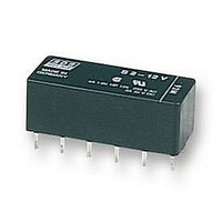
Manufacturer Part Number
S2-L2-12VDC
Description
RELAY, PCB, DPNO & DPNC
Manufacturer
PANASONIC EW
Datasheet
1.S2-12VDC.pdf
(5 pages)
Specifications of S2-L2-12VDC
Relay Type
Power
Coil Voltage Vdc Nom
12V
Contact Current Max
4A
Contact Voltage Ac Nom
250V
Contact Voltage Dc Nom
30V
Coil Resistance
720ohm
Coil Type
DC Coil, Sensitive
Coil Current
16.7mA
Nom
RoHS Compliant
Contact Configuration
DPNO
Rohs Compliant
Yes


NOTES
1. Special use of 2 coil latching types: 2
ways can be considered if 2 coil latching
types are used as 1 coil latching types.
(A) Reverse polarity is applied to the set
coil of 2 coil latching type.
(B) By shorting terminals 12 and 7, apply
plus to 1, minus to 6 at set and plus to 6,
minus to 1 at reset. Applied coil voltage
should be the same as the nominal.
Operating power will be reduced to one-
half.
CAUTIONS FOR USE
Based on regulations regarding insulation distance, there is a
restriction on same-channel load connections between terminals
No. 2, 3 and 4, 5, as well as between No. 8, 9 and 10, 11. See
the figure below for an example.
For Cautions for Use, see Relay Technical Information (see catalog).
en_ds_61105_0000: 130804D
Reset position of 2a2b type
-
12
1
11
2
10
3
4
9
Between 2, 3 and 4, 5:
Between 10, 11 and 8, 9:
5
8
6
11
7
+
2 3
10
No good
different channels, therefore not possible
different channels, therefore not possible
9
4
5
2. Soldering operations should be
accomplished as quick as possible;
within 10 seconds at 250°C
temperature or 3 seconds at 350°C
662°F. The header portion being sealed
with epoxy resin, undue subjection to
heat may cause loss of seal. Solder
should not be permitted to remain on the
header.
8
Between 2, 3 and 4, 5:
Between 10, 11 and 8, 9:
11
2
10
3
Good
same channels, therefore possible
same channels, therefore possible
482°F
4
9
5
8
solder
S
5
Related parts for S2-L2-12VDC
Image
Part Number
Description
Manufacturer
Datasheet
Request
R

Part Number:
Description:
POWER RELAY DPST-NO/NC 24VDC 4A PC BOARD
Manufacturer:
PANASONIC EW
Datasheet:

Part Number:
Description:
RELAY, PCB, DPNO & DPNC
Manufacturer:
PANASONIC EW
Datasheet:


Part Number:
Description:
POWER RELAY, 24VDC, 30A, SPST-NO
Manufacturer:
PANASONIC EW
Datasheet:

Part Number:
Description:
POWER RELAY, SPDT, 12VDC, 10A, PC BOARD
Manufacturer:
PANASONIC EW

Part Number:
Description:
POWER RELAY, 24VDC, 5A, SPST-NO, PCB
Manufacturer:
PANASONIC EW
Datasheet:


Part Number:
Description:
SIGNAL RELAY, DPDT, 4.5VDC, 1A, SMD
Manufacturer:
PANASONIC EW
Datasheet:

Part Number:
Description:
SIGNAL RELAY, DPDT, 4.5VDC, 1A, THD
Manufacturer:
PANASONIC EW
Datasheet:

Part Number:
Description:
MINIATURE RELAY, DPDT, 24VDC, 2A, THD
Manufacturer:
PANASONIC EW

Part Number:
Description:
SIGNAL RELAY, DPDT, 5VDC, 2A, PC BOARD
Manufacturer:
PANASONIC EW
Datasheet:


Part Number:
Description:
PHOTOMOS RELAY, 60VDC, 400mA
Manufacturer:
PANASONIC EW
Datasheet:

Part Number:
Description:
PHOTOMOS RELAY, 400V, 150mA
Manufacturer:
PANASONIC EW
Datasheet: