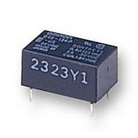
G6E-134P-US 24DC Omron, G6E-134P-US 24DC Datasheet - Page 4

G6E-134P-US 24DC
Manufacturer Part Number
G6E-134P-US 24DC
Description
SIGNAL RELAY, SPDT, 24VDC, 3A, THD
Manufacturer
Omron
Datasheet
1.G6E-134P-US_24DC.pdf
(5 pages)
Specifications of G6E-134P-US 24DC
Contact Configuration
SPDT
Contact Current Max
3A
Contact Voltage Ac Nom
125V
Contact Voltage Dc Nom
30V
Coil Voltage Vdc Nom
24V
Coil Type
DC, Monostable
Coil Current
8.3mA
Lead Free Status / RoHS Status
Lead free / RoHS Compliant
Engineering Data
Dimensions
Note: 1. All units are in millimeters unless otherwise indicated.
G6EU-134P-US
G6EU-194P-US
G6E-134P-US
G6E-194P-US
G6E-134C-US
G6E-194C-US
Maximum Switching Power
Text
PCB Signal Relay – G6E
188
2. Orientation marks are indicated as follows:
DC inductive load
(L/R = 7 ms)
AC inductive load
(cosf = 0.4)
Switching voltage (V)
DC resistive load
3.16
AC resistive
load
1.6
1.6
1.6
0.6
2.86
0.6
0.6
5.08
5.08
5.08
16 max.
(15.9) *
16 max.
(15.9) *
16 max.
(15.9) *
7.62
7.62
7.62
100,000
50,000
10,000
1,000
3,000
5,000
3,000
*Average value
*Average value
*Average value
*Average value
500
300
100
50
Endurance
0.25
0.25
0.25
Switching current (A)
30-VDC inductive load
(L/R = 7 ms)
10 max.
(9.9) *
7.62
10 max.
(9.9) *
10 max.
(9.9) *
7.62
7.62
125-VAC inductive load
(cosφ = 0.4)
30-VDC resistive
load
0.3
0.3
0.3
125-VAC
resistive load
3.5
3.5
8 max.
(7.9) *
8 max.
(7.9) *
8 max.
(7.9) *
Note: The maximum coil voltage refers to the maxi-
Five, 1.0-dia. holes
mum value in a varying range of operating
power voltage, not a continuous voltage.
(1.65)
Terminal Arrangement/
Internal Connections
(Bottom View)
Terminal Arrangement/
Internal Connections
(Bottom View)
Ambient Temperature vs.
Maximum Coil Voltage
G6E-134P-US
Only at 48VDC
Mounting Holes
(Bottom View)
Mounting Holes
Mounting Holes
(Bottom View)
(B tt
Tolerance: ±0.1
5.08
Ambient temperature (°)
-
1 +
+ 1
12 10
12 10
S
7.62
G6E-134P-US
G6EK-134P-US
G6EU-134P-US
Vi
R
+
- 6
- 6
)
7
7
7.62
(1.19)


