TDR782XDXA-110A Magnecraft / Schneider Electric, TDR782XDXA-110A Datasheet

TIME DELAY RELAY, 4PDT, 100H, 110VAC

TDR782XDXA-110A

Manufacturer Part Number
TDR782XDXA-110A
Description
TIME DELAY RELAY, 4PDT, 100H, 110VAC
Manufacturer
Magnecraft / Schneider Electric
Datasheets

Specifications of TDR782XDXA-110A

Contact Configuration
4PDT
Nom Input Voltage
110VAC
Delay Time Range
0.1s To 100h
Timing Adjustment
Knob
Relay Mounting
DIN Rail
Relay Terminals
Quick Connect
No. Of Timing Functions
1
Display Type
Time-Delay Relay
Supply Voltage
110 V
Timing Range
0.1 s to 100 Hrs
Contact Form
4PDT
Termination Style
Quick Connect
Current, Rating
3 A
Function
Timing
Mounting Type
Socket
Relay Type
Electro Mechanical
Standards
UL, CSA, CE
Termination
Plug-In
Timer Type
On Delay
Voltage, Control
110 VAC
Tolerance
Mechanical Setting 5%
Reset Time
Maximum 50 ms
Carry Current
3A
Coil Voltage Vac Nom
110V
Rohs Compliant
Yes
Lead Free Status / RoHS Status
Lead free / RoHS Compliant
Time Delay Relays – Application Data
Definition:
Time Delay is defined as the controlled period between the functioning of two events. A Time Delay relay is a combination
of an electromechanical output relay and a control circuit. The control circuit is comprised of solid state components and
timing circuits that control operation of the relay and timing range. Typical time delay functions include On-Delay, Repeat
cycle (starting off), Interval, Off-Delay, Retriggerable One Shot, Repeat cycle (starting on), Pulse Generator, One Shot,
On/Off Delay, and Memory Latch. Each function is explained in the table below. Time delay relays have a broad
choice of timing ranges from less than one second to many days. There are many choices of timing adjustments from
calibrated external knobs, DIP switches, thumbwheel switches, or recessed potentiometer. The output contacts on the
electromechanical output relay are direct wired to the output terminals. The contact load ratings are specified for each
specific type of time delay relay.
Understanding the differences between all the functions available in time delay relays can sometimes be a daunting task.
When designing circuits using time delay relays questions such as:
“What initiates a time delay relay?”
“Does the timing start with the application or release of voltage?”
“When does the output relay come on?”
must be asked.
Time delay relays are simply control relays with a time delay built in. Their purpose is to control an event based on time.
The difference between relays and time delay relays is when the output contacts open & close: on a control relay, it
happens when voltage is applied and removed from the coil; on time delay relays, the contacts will open or close before
or after a pre-selected, timed interval.
Typically, time delay relays are initiated or triggered by one of two methods:
• application of input voltage (On Delay, Interval On, Flasher, Repeat Cycle, Delayed Interval & Interval/Flasher).
• opening or closing of a trigger signal (Off Delay, Single Shot & Watchdog).
These trigger signals can be one of two designs:
• a control switch (dry contact), i.e., limit switch, push button, float switch, etc.
• voltage (commonly known as a power trigger).
To help understand, some definitions are important:
Input Voltage: Control voltage applied to the input terminals (see wiring diagrams below). Depending on the function,
input voltage will either initiate the unit or make it ready to initiate when a trigger signal is applied.
Trigger Signal: On certain timing functions, a trigger signal is used to initiate the unit after input voltage has been applied.
As noted above, this trigger signal can either be a control switch (dry contact switch) or a power trigger (voltage).
Output (Load): Every time delay relay has an internal relay (usually mechanical) with contacts that open & close to control
the load. They are represented by the dotted lines in the wiring diagrams. Note that the user must provide the voltage to
power the load being switched by the output contacts of the time delay relay.
The following tables contain both written and visual descriptions on how the common timing functions operate. A Timing
Chart shows the relationship between Input Voltage, Trigger Signal (if present) and Output Contacts.
5/2
M agne cr aft S olu tion Guide 1 0 5 A

Related parts for TDR782XDXA-110A

TDR782XDXA-110A Summary of contents

Page 1

... Time delay relays are simply control relays with a time delay built in. Their purpose is to control an event based on time. The difference between relays and time delay relays is when the output contacts open & close control relay, it happens when voltage is applied and removed from the coil ...

Page 2

... REPEAT CYCLE and time delay t begins. When time delay t is complete, contacts return to Starting On their shelf state for time delay t. This cycle will repeat until input voltage U is removed. Trigger switch is not used in this function. G. Upon application of input voltage U, a single output pulse of 0.5 seconds is PULSE delivered to relay after time delay t ...

Page 3

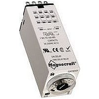
... Advantages of the TDR782 Time Delay Relay Socket Compatible Mounts Directly On a DIN Rail or Panel. Mating Hold-Down Clip Available Secures Relay to Socket. 5/14 Time Setting Marked with Both IEC Select Between and NEMA Markings 7 Different Time Universal Socket Scales. Compatibility. Excellent Immunity to Interference Conforms to IEC 61812-1/A11 ...

Page 4

... System Solution! The miniature TDR782 series is a single-function, single-voltage time delay relay with multiple time ranges for the ultimate in packaging the most within the smallest space possible in a panel or on the DIN rail. The TDR782 features a screw driver adjust- able knob which allows the user to choose timing ranges and a large knob on top for fine tuning the timing setting ...

Page 5

... TDR782 Time Delay Relay/DPDT, 4PDT Amp Rating UL Recognized WHITE File No. E191122 General Specifications (@ 25°C) Output Characteristics Number and type of Contacts Contact Material Current rating Maximum permissible current Minimum Switching Requirement Indication Input Characteristics Standard Voltage Operating Range Maximum consumption Indication Timing Characteristics ...

Page 6

... U is removed. Control switch is not used in this mode. Standard Part Numbers TDR782XBXA-12D TDR782XBXA-24D TDR782XBXA-24A TDR782XBXA-110A TDR782XBXA-230A TDR782XDXA-12D TDR782XDXA-24D TDR782XDXA-24A TDR782XDXA-110A TDR782XDXA-230A Part Number Builder Series TDR782 = 782 Miniature Timer NOTE: Terminal size is 0.105 x 0.020 0.8 (21 ...

Related keywords