H3YN-2-200/230AC Omron, H3YN-2-200/230AC Datasheet - Page 12
H3YN-2-200/230AC
Manufacturer Part Number
H3YN-2-200/230AC
Description
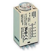
TIMER, MULTIFUNCTION, DPDT
Manufacturer
Omron
Datasheet
1.H3YN-2-24DC.pdf
(12 pages)
Specifications of H3YN-2-200/230AC
Contact Configuration
DPCO
Nom Input Voltage
230VAC
Delay Time Range
0.1s To 10min
Adjustment Type
Knob
Relay Mounting
Plug-In
Svhc
No SVHC (15-Dec-2010)
Coil Voltage Vac Nom
230V


Cat. No. L089-E1-1A
OMRON Corporation
Supervisory Control Devices Division
28th Fl., Crystal Tower Bldg.,
1-2-27, Shiromi, Chuo-ku,
Osaka 540-6028 Japan
Phone: (81)6-949-6035 Fax: (81)6-949-6069
H3YN
Precautions
The operating voltage will increase when using the H3YN continu-
ously in any place where the ambient temperature is in a range of
45 C to 50 C. Supply 90% to 110% of the rated voltages (at
12 VDC: 95% to 110%).
Do not leave the H3YN in time-up condition for a long period of time
(for example, more than one month in any place where the ambient
temperature is high), otherwise the internal parts (aluminum elec-
trolytic capacitor) may become damaged. Therefore, the use of the
H3YN with a relay as shown in the following circuit diagram is rec-
ommended to extend the service life of the H3YN.
The H3YN must be disconnected from the Socket when setting the
DIP switch, otherwise the user may touch a terminal imposed with a
high voltage and get an electric shock.
Do not connect the H3YN as shown in the following circuit diagram
on the right hand side, otherwise the H3YN’s internal contacts differ-
ent from each other in polarity may become short-circuited.
Use the following safety circuit when building a self-holding or self-
resetting circuit with the H3YN and an auxiliary relay, such as an MY
Relay, in combination.
In the case of the above circuit, the H3YN will be in pulse operation.
Therefore, if the circuit shown on page 11 is used, no auxiliary relay
will be required.
12
Correct
ALL DIMENSIONS SHOWN ARE IN MILLIMETERS.
To convert millimeters into inches, multiply by 0.03937. To convert grams into ounces, multiply by 0.03527.
In the interest of product improvement, specifications are subject to change without notice.
Incorrect
: H3YN
Auxiliary relay:
MY Relay
H3YN
MY Relay
Do not set to the minimum setting in the flicker modes, otherwise the
contact may become damaged.
Be careful not to apply any voltage to the terminal screws on the
back of the Timer. Mount the product so that the screws will not
come in contact with the panel or metal parts.
Do not use the H3YN in places where there is excessive dust, corro-
sive gas, or direct sunlight.
Do not mount more than one H3YN closely together, otherwise the
internal parts may become damaged. Make sure that there is a
space of 5 mm or more between any H3YN models next to each oth-
er to allow heat radiation.
The internal parts may become damaged if a supply voltage other
than the rated ones is imposed on the H3YN.
Precautions for VDE Conformance
The H3YN as a built-in timer conforms to VDE 0435/P2021 provided
that the following conditions are satisfied.
Handling
Do not touch the DIP switch while power is supplied to the H3YN.
Before dismounting the H3YN from the Socket, make sure that no
voltage is imposed on any terminal of the H3YN.
Wiring
The power supply for the H3YN must be protected with equipment
such as a breaker approved by VDE.
Only a load with basic isolation can be connected to the output con-
tact. The H3YN is a model with basic isolation. Therefore, the H3YN
and the load will ensure reinforced isolation, thus meeting VDE
standards.
Insulation requirement: Overvoltage category II,
Output terminals next to each other on the H3YN-4, H3YN-41,
H3YN-4Z, or H3YN-41-Z must have the same electric potential.
pollution degree 2
(with a clearance of 1.5 mm and a creep-
age distance of 2.5 mm at 240 VAC)
Printed in Japan
1298-1M (0296)
H3YN
Related parts for H3YN-2-200/230AC
Image
Part Number
Description
Manufacturer
Datasheet
Request
R

Part Number:
Description:
Relay; SSR; Timing; Multi-Function; DPDT; Cur-Rtg 5A; Ctrl-V 200-230AC; Vol-Rtg 250AC
Manufacturer:
Omron Automation
Datasheet:
Part Number:
Description:
Relay; SSR; Timing; Multi-Function; DPDT; Cur-Rtg 5A; Ctrl-V 100-120AC; Vol-Rtg 250AC
Manufacturer:
Omron Automation
Datasheet:
Part Number:
Description:
Relay; SSR; Timing; Multi-Function; DPDT; Cur-Rtg 5A; Ctrl-V 24DC; Vol-Rtg 250AC
Manufacturer:
Omron Automation
Datasheet:
Part Number:
Description:
Relay; SSR; Timing; Multi-Function; 4PDT; Cur-Rtg 3A; Ctrl-V 200-230AC; Vol-Rtg 250AC
Manufacturer:
Omron Automation
Datasheet:

Part Number:
Description:
TIMER MINI MULTI-TIME DPDT
Manufacturer:
Omron
Datasheet:
Part Number:
Description:
Relay; SSR; Timing; Multi-Function; 4PDT; Cur-Rtg 3A; Ctrl-V 100-120AC; Vol-Rtg 250AC
Manufacturer:
Omron Automation
Datasheet:
Part Number:
Description:
Relay; SSR; Timing; Multi-Function; 4PDT; Cur-Rtg 3A; Ctrl-V 24DC; Vol-Rtg 250AC
Manufacturer:
Omron Automation
Datasheet:
Part Number:
Description:
Relay; SSR; Timing; Multi-Function; DPDT; Cur-Rtg 5A; Ctrl-V 100-120AC; Vol-Rtg 250AC
Manufacturer:
Omron Automation
Datasheet:
Part Number:
Description:
Relay; SSR; Timing; Multi-Function; 4PDT; Cur-Rtg 3A; Ctrl-V 100-120AC; Vol-Rtg 250AC
Manufacturer:
Omron Automation
Datasheet:

Part Number:
Description:
TIMER, ON-DELAY, 12VDC, 30M
Manufacturer:
Omron
Datasheet:
Part Number:
Description:
TIMER, ON-DELAY, 24VDC, 60S
Manufacturer:
Omron
Datasheet:
Part Number:
Description:
G6S-2GLow Signal Relay
Manufacturer:
Omron Corporation
Datasheet: