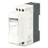
RE7TP13BU TELEMECANIQUE, RE7TP13BU Datasheet - Page 12

RE7TP13BU
Manufacturer Part Number
RE7TP13BU
Description
TIMER, ON-DELAY
Manufacturer
TELEMECANIQUE
Datasheet
1.RE7TL11BU.pdf
(22 pages)
Specifications of RE7TP13BU
Contact Configuration
DPCO
Nom Input Voltage
240V
Delay Time Range
0.05s To 300h
Relay Mounting
DIN Rail
Coil Voltage Vac Nom
250V
Contact Current Ac Max
8A
Contact Current Dc Max
8A
1
4
Schemes
Terminal blocks
RE7-RL13BU
Recommended application schemes
Start on de-energisation
RE7-RB
Start by external control
RE7-RA
Setting-up procedure
28 (24)
A1
Y1
18
40
No galvanic insulation between supply terminals A1, A2, B1, B2 and control inputs X1, Y1, Z1, Z2.
2
25 (21)
26 (22)
A2
A1
A2
15
16
A1
1
2
3
30 s
Y1
B1
B2
Z2
A2
x. %
Zelio Time - timing relays
Relay output, width 22.5 mm, universal
Off-delay relays
Schemes, setting-up
RE7-RB11MW
Start by low level
external control
RE7-RM and RL
+
–
A1
18
15
16
B1
1
2
3
4
Adjustment of the time delay
- Select the timing range immediately greater than the time required, using selector switch 2.
Example: required time 12 s; range selected 30 s.
- Using potentiometer
1
A2
= ––––––
Potentiometer for fine adjustment of the time delay, graduated in % of range max. setting 2.
Timing range selector:
- 10-position (RE7-RA, RM, RL)
- 7-position (RE7-RB)
Switch for converting the second changeover contact to instantaneous mode (RE7-RL13BU).
LEDs, depending on the model:
- Green LED U/T: flashes during the time delay period, permanently on outside the time delay period.
- Yellow LED R1: on when 1
- Yellow LED R2: on when 2
- RE7-RBiiMW: the green LED does not flash during the time delay period and there is only one yellow
A2
B2
B2
LED (R).
t x 100
A2
Y1
2
A1
Y1
Z2
i.e.
12 x 100
––––––– = 40
1
30
display the required time value as a % of value 2.
RE7-RB13MW
RE7-RA and RM
Remote control
of partial stop
+
–
nd
st
A1
Z1
18
28
relay is energised.
relay is energised.
15
16
25
26
0.05…1 s
0.15…3.s
0.05…1 s
0.15…3.s
B1
A2
B1
B2
A2
Y1
Z2
A2
A1
0.5…10 s 5…100 s
1.5…30 s 15…300 s
0.5…10 s 5…100 s
1.5…30 s 15…300 s
X1
Z2
RE7-RM11BU and RE7-RA11BU
Potentiometer wiring
Wiring precautions
RE7-RM and RL
A1
Z1
X1
18
A2
A2
Z1
Z2
15
Y1
16
Te
1.5…30 min
15…300 min 15…300 h
1.5…10 min
B1
B2
Z2
A2
Z2
1.5…30 h
2/25
2


