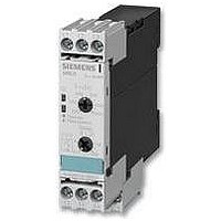
3UG4513-1BR20 SIEMENS, 3UG4513-1BR20 Datasheet - Page 21
3UG4513-1BR20
Manufacturer Part Number
3UG4513-1BR20
Description
SSR, DIN RAIL, 690VAC, 690VAC, 5A
Manufacturer
SIEMENS
Datasheet
1.3UG4513-1BR20.pdf
(26 pages)
Specifications of 3UG4513-1BR20
Control Voltage Range
160V To 690V
Operating Voltage Range
200Vrms To 690Vrms
Load Current
5A
Control Voltage Type
AC
Relay Terminals
Screw
Length/height, External
82mm
External Width
22.5mm
Load Voltage Max
400V
Load Current Rms Max
5A
Rohs Compliant
Yes
External Depth
86mm
Lead Free Status / RoHS Status
Lead free / RoHS Compliant


■
■
Overview
Function
The monitoring relay measures the insulation resistance
between the positive and negative supply voltage in an
ungrounded DC voltage network and a corresponding
protective conductor.
The measurement is based on the DC residual current
measurement principle. The response value can be adjusted
steplessly in the range from 10 ... 110 kW and thus can be
adapted to the corresponding conditions. If the insulation
resistance falls below the set response value, the output relay
triggers (depending on the setting of the open/closed-circuit
principle selector switch) and a fault LED lights up.
A ground fault is evaluated separately for L+ and L- and
indicated by means of a corresponding LED.
Note:
Due to the measurement principle, a symmetrical ground fault
on terminals L+ and L- cannot be evaluated.
Test function
A ground fault can be simulated using the Test L+ and Test
L- buttons on the front. If the test button is pressed for at least
1 s, the status of the output relay changes and the
corresponding fault LED lights up.
An external test button can be connected to terminals Y1-Y3 for
L+ and terminals Y4-Y3 for L-. The function is triggered by
means of a NO contact.
Fault storage and RESET
If terminals Y2 and Y3 are linked, the monitoring relay is set to
fault storage mode.
If the insulation resistance falls below the set value, the output
relay triggers (depending on the setting of the open/closed
circuit selector switch), and stays in this state even if the insu-
lation resistance rises again above the hysteresis value (typical:
2 times the set value). This fault storage can be deleted by
pressing and releasing the L+ RESET button, opening the
Y2-Y3 connection or by switching off the supply voltage.
3UG Monitoring Relays for Electrical and Additional Measurements
© Siemens AG 2007
Relay for monitoring the insulation resistance between
ungrounded pure DC networks and a protective conductor
• Measuring principle for differential current measurement
• Response value can be set continuously from 10 ... 110 kW
• Selectable
• Front selector switch for open-circuit and closed-circuit
• Test function with test buttons on the front for L+ and L-
• Switching output: 1 CO contact
• Insulation fault indicator for L+ and L- through two red LEDs
• Supply voltage indication with a green LED
• Electro-magnetically compatible according to EN 50081 and
Open/closed-circuit principle selector switch
The principle of operation of the output relay can be adjusted by
means of a selector switch on the front panel.
If the relay is to respond in the event of a fault (contact symbol
open), the open-circuit principle must be selected. If the relay
however is to trigger in the event of a fault (contact symbol
closed), the closed-circuit principle must be selected.
Note:
The position of the selector switch has no effect upon the fault
LEDs. The LEDs always light up if the insulation resistance on
L+ or L– falls below the set value.
- Auto reset function with hysteresis or
- Storage of the tripping operation
principle for the output relay
and over terminal connections
EN 61000-6-2.
1
2
3
4
5
6
7
8
1
2
3
4
5
6
7
8
Y3/Y4
Y1/Y3
Y2/Y3
L+/PE
L-/PE
Open-
circuit/
closed
circuit
principle
11/14
11/12
= Supply voltage
= Button on front – Reset L+ and L-/Test L+
= Button on front – Test L – Test remote connection – Test L
= Test remote connection – Test L+
= Test remote connection – Store, reset
= Insulation resistance R of supply
= Switch on front
= NO contact
A1/A2
set response value R
Open-circuit/closed-circuit principle
R
R
t
R
Test
value
Hyst
R
= approx. 1 s
= typically 2 x R
Hyst
Monitoring Relays
for ungrounded DC networks
Siemens LV 1 T · 2007
x
Insulation monitoring
t
Test
> I
NSB0_01395a
s
7/81
Related parts for 3UG4513-1BR20
Image
Part Number
Description
Manufacturer
Datasheet
Request
R

Part Number:
Description:
Intel 80C32 - Siemens SAB-C501, Nearest Equivalent Replacement
Manufacturer:
Siemens Semiconductor Group
Part Number:
Description:
IGBT MODULE
Manufacturer:
Siemens Semiconductor Group
Datasheet:
Part Number:
Description:
SIMOPAC Module (Power module Single switch N channel Enhancement mode)
Manufacturer:
Siemens Semiconductor Group
Datasheet:
Part Number:
Description:
(BSMxxx) TRANSISTOR
Manufacturer:
Siemens Semiconductor Group
Datasheet:
Part Number:
Description:
SIMOPAC Module (Power module Single switch N channel Enhancement mode)
Manufacturer:
Siemens Semiconductor Group
Datasheet:
Part Number:
Description:
main ratings
Manufacturer:
Siemens Semiconductor Group
Datasheet:
Part Number:
Description:
Manufacturer:
Siemens Semiconductor Group
Datasheet:
Part Number:
Description:
Manufacturer:
Siemens Semiconductor Group
Datasheet:
Part Number:
Description:
Manufacturer:
Siemens Semiconductor Group
Datasheet:
Part Number:
Description:
ICs for Consumer Electronics
Manufacturer:
Siemens Semiconductor Group
Datasheet:
Part Number:
Description:
Video and Sound IF with V & S SCART
Manufacturer:
Siemens Semiconductor Group
Datasheet:
Part Number:
Description:
Manufacturer:
Siemens Semiconductor Group
Datasheet:
Part Number:
Description:
Multistandard Sound IF
Manufacturer:
Siemens Semiconductor Group
Datasheet:
Part Number:
Description:
MULTISTANDARD AM FM SOUND IF IC
Manufacturer:
Siemens Semiconductor Group
Datasheet: