G3NA-220B 5-24DC Omron, G3NA-220B 5-24DC Datasheet - Page 8
G3NA-220B 5-24DC
Manufacturer Part Number
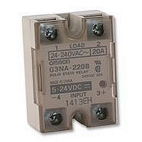
G3NA-220B 5-24DC
Description
SSR, 20A
Manufacturer
Omron
Datasheet
1.G3NA-205B_5-24DC.pdf
(8 pages)
Specifications of G3NA-220B 5-24DC
Control Voltage Range
5Vdc To 24 Vdc
Operating Voltage Range
19VAC To 264VAC
Load Current
20A
Isolation Voltage
2500V
Control Voltage Type
DC
Svhc
No SVHC (15-Dec-2010)
Approval Bodies
UL, CSA
Control Voltage Dc
RoHS Compliant
Relay Terminals
Screw
Rohs Compliant
Yes


G3NA
Precautions
Refer to pages 11 to 19 for general precautions.
Load Connection
For an AC load, use a power supply rated at 50 or 60 Hz.
The maximum operating frequency is 10 Hz.
The G3NA has a built-in varistor for overvoltage protection.
Zero Cross Function
An SSR with a zero cross function operates when an AC load volt-
age reaches the zero point or its vicinity. This reduces clicking
noises when the load is input, and minimizes the influence of an in-
ductive load, such as a lamp, heater, or motor, on the power supply
because the inrush current of the load is reduced. This can also
minimize the scale of the inrush current protection circuit.
At a low applied voltage, such as 24 VAC, the load current is not fully
supplied. When the Unit is switched ON, the voltage required to
power the Unit deprives the output signal of the necessary voltage
level and thus creates loss time. The lower the load voltage is, the
greater the loss time is. This condition, however, will not create any
serious problems.
For a DC or L load, a diode should be connected in parallel the load
to absorb the counter electromotive force of the load.
8
R99-11
Cat. No. K067-E1-1C
Input
Output (load voltage)
Input
SSR
ON
OFF
21
ALL DIMENSIONS SHOWN ARE IN MILLIMETERS.
To convert millimeters into inches, multiply by 0.03937. To convert grams into ounces, multiply by 0.03527.
Loss time
12.5
16
8
4
Load
5
4.6
Load power
supply
When attaching a heat sink to the G3NA, apply Silicone Grease or
equivalent heat conductive grease on the heat sink. (Toshiba Sili-
con, Shinetsu Silicon, etc.)
Tighten the mounting screws of the heat sink with a torque of 0.78 to
0.98 N m.
EN55011 Measurement of Mains Terminal Disturbance
Voltage
The G3NA-UTU conforms to EN55011 standards when a capacitor
is connected to the load power supply as shown in the following cir-
cuit diagram.
Recommended Capacitor:
Nissei Denki’s MKT-series R40 (1 F)
The output terminal side of the G3NA-D210B is connected to a built-
in diode for protecting the SSR from damage that may result from
reverse connection. The SSR, however, cannot withstand one min-
ute or more if the wires are connected in reverse order. Therefore,
pay the utmost attention not to make polarity mistakes on the load
side.
56
Use Mounting Bracket R99-11 so that the
G3NA-240B can be mounted with the same pitch
as that of the G3N-240B.
Input
G3NA-UTU
Output
Load
G3NA
Related parts for G3NA-220B 5-24DC
Image
Part Number
Description
Manufacturer
Datasheet
Request
R

Part Number:
Description:
RELAY SSR 20A 5-24VDC ZERO CROSS
Manufacturer:
Omron
Datasheet:
Part Number:
Description:
RELAY SSR 20A 100-120VAC ZERO
Manufacturer:
Omron
Datasheet:
Part Number:
Description:
RELAY SSR 20A 200-240VAC ZERO
Manufacturer:
Omron
Datasheet:

Part Number:
Description:
SOLID STATE RELAY
Manufacturer:
Omron
Datasheet:

Part Number:
Description:
RELAY SSR 20A 120VAC
Manufacturer:
Omron
Datasheet:

Part Number:
Description:
RELAY SSR 20A 230VAC
Manufacturer:
Omron
Datasheet:

Part Number:
Description:
SSR, 20A
Manufacturer:
Omron
Datasheet:

Part Number:
Description:
SOLID STATE RELAY/TUV MARKINGS
Manufacturer:
Omron

Part Number:
Description:
G6S-2GLow Signal Relay
Manufacturer:
Omron Corporation
Datasheet:
Part Number:
Description:
Compact, Low-cost, SSR Switching 5 to 20 A
Manufacturer:
Omron Corporation
Datasheet:
Part Number:
Description:
Manufacturer:
Omron Corporation
Datasheet: