E30KLA1 EATON CUTLER HAMMER, E30KLA1 Datasheet - Page 227
E30KLA1
Manufacturer Part Number
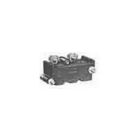
E30KLA1
Description
SWITCHING ELEMENT, 1NO, 10A, SCREW
Manufacturer
EATON CUTLER HAMMER
Datasheet
1.10250T102.pdf
(320 pages)
Specifications of E30KLA1
No. Of Poles
1
Contact Current Max
10A
Contact Voltage Ac Max
600V
Contact Voltage Dc Max
250V
Switch Terminals
Screw
Circuitry
SPST-NO
For Use With
E30 Series Pushbuttons & Indicating Lights


Push-Pull Operators
An illuminated push-pull
pushbutton unit, arranged for
one-hole mounting, can
replace two pushbuttons and
a pilot light or the non-
illuminated form can replace
two pushbuttons. These units
are available in three basic
types:
●
●
Two-Position Maint.
Push-Pull
Maintained—(Two-
position). Maintains in the
pulled or pushed position
until manually actuated to
the opposite mode.
Momentary—(Three-
position). Spring returns to
an intermediate position
when pulled or pushed and
released.
Push-Pull Operator Components
Type of Operator
Two-Position Operator without Lens
Maintained push-pull
Three-Position Operator without Lens
Momentary push-pull
Maintained push-momentary pull
Momentary push-pull
Notes
Use NEMA 4X 10250T operators where exposed to ultraviolet light, see Pages 140–212.
See Typical Applications on Page 162.
E34GHB.
Shown without button on lens.
Maximum of two blocks, four circuits. Special function contact blocks shown on Page 245 CANNOT be used with three-position push-pull operators E34GEB, E34GFB or
●
The operators, buttons,
contact blocks, etc., are
offered as building block
components that can be
intermixed to satisfy many
requirements. This minimizes
the need for a varied and
costly inventory.
Momentary Pull,
Maintained Push—(Three-
position). Spring returns to
intermediate position when
pulled. Maintains in pushed
position until manually
returned to intermediate
(ready to reset) position.
Maintained stop holds
circuit open and will
prevent other series
connected operators from
starting the system.
Operator Position and Circuit Arrangement
Out—Pull
Contact Block Mounting Location
A
O
X
O
X
O
X
O
X
O
X
O
X
O
X
O
X
30.5 mm Corrosion Resistant Watertight/Oiltight—E34
Pushbuttons and Indicating Lights
or
or
or
or
Control Products Catalog CA08102001E—August 2010 www.eaton.com
B
O
X
O
X
O
X
O
X
O
X
O
X
O
X
O
X
Intermediate
A
No intermediate
position
O
O
O
O
O
O
O
O
O
O
O
O
Application Guide
To assist in the selection of
contact blocks, the sketch
below shows pictorially by
symbols A and B locations of
contact circuits after
assembly of contact blocks
and adapter to the operator.
The table below shows the
effect of the push and pull
operations on either NO or
NC contacts. (X = contact
closed, O = contact open).
Contact Circuit Locations
or
or
or
B
O
X
O
X
O
X
O
X
O
O
O
O
Locating Nib
In—Push
A
X
O
X
O
X
O
X
O
X
O
X
O
X
O
X
O
or
or
or
or
A
B
B
X
O
X
O
O
O
O
O
X
O
O
O
O
O
X
O
Contact Block
1NO
1NC
2NO
2NC
1NO
1NC
2NO
2NC
1NO
1NC
2NO
2NC
1NO
1NC
2NO
2NC
E34GDB
E34GEB
Catalog Number
E34GFB
E34GHB
47.7
227
47
47
47
47
47
47
47
47
47
47
47
47
47
47
47
47
47
47
47
47
47
47
47
47
47
47
47
47
47
47
Related parts for E30KLA1
Image
Part Number
Description
Manufacturer
Datasheet
Request
R

Part Number:
Description:
PROGRAMMABLE LOGIC CONTROLLER
Manufacturer:
EATON CUTLER HAMMER
Part Number:
Description:
Pm Power Pro 3000/5000 A-B Accel/On Interface
Manufacturer:
EATON CUTLER HAMMER
Part Number:
Description:
Handle Tie Bar For (2) - 1 Pole Type BR Breakers
Manufacturer:
EATON CUTLER HAMMER
Part Number:
Description:
Type CH Breaker 150A/2 Pole 120/240V 10K
Manufacturer:
EATON CUTLER HAMMER
Part Number:
Description:
Tenant Branch Breaker 125A/3 Pole 120/240V 42K
Manufacturer:
EATON CUTLER HAMMER
Part Number:
Description:
Type CL Breaker 25A/1Pole 120/240V 10K-Classified 1" Ckt Bkr
Manufacturer:
EATON CUTLER HAMMER
Part Number:
Description:
FD BREAKER 1P 80 AMP WITH LOAD ONLY TERMINALS
Manufacturer:
EATON CUTLER HAMMER
Part Number:
Description:
GD 2 POLE BREAKER, 25 AMP, SINGLE PACKED
Manufacturer:
EATON CUTLER HAMMER
Part Number:
Description:
Handle Tie Bar For (2) - 1 Pole Type BR Breakers
Manufacturer:
EATON CUTLER HAMMER
Part Number:
Description:
Type CL Breaker 25A/1Pole 120/240V 10K-Classified 1" Ckt Bkr
Manufacturer:
EATON CUTLER HAMMER