704-900.5 EAO, 704-900.5 Datasheet - Page 25
704-900.5
Manufacturer Part Number
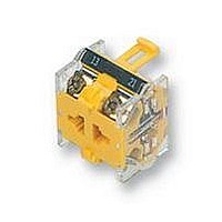
704-900.5
Description
CONTACT BLOCK, 1NO/1NC
Manufacturer
EAO
Datasheet
1.704-900.3.pdf
(38 pages)
Specifications of 704-900.5
No. Of Poles
2
Contact Voltage Ac Max
500V
Svhc
No SVHC (18-Jun-2010)
Contact Current Rating
10A
Terminal Type
Screw
Contact Configuration
1 N/O + 1 N/C
Current Rating
10A
Rohs Compliant
Yes
Lead Free Status / RoHS Status
Lead free / RoHS Compliant
For Use With
-000 A


Technical Data
switching system
material
mechanical characteristics
actuator with snap-action switching element
Self-cleaning, double-break, snap action switching system (with
contact gap 2 x 0.5 mm).
1 normally closed or 1 normally open contact per element.
snap-action switching elements with soldering terminals at the
sides: up to 4 switching element can be on a pushbutton (max. 4
normally closed and 4 normally open contacts).
snap-action switching element with axial plug-in terminals 2,8 mm
not stachable, only 1 switching element can be on a pushbutton.
actuator case
polyamide
material of contacts
gold-plated silver
switching element
plug-in-/soldering terminal
diallylphthalate DAP, polyamide 66, polysulfone, heat-resistant and
self-extinguishing
soldering terminal: PA 6.6 Ultramid
actuating force
3.5-5.5 N, depending on the number of switching elements
actuating torque
measured at the key or lever of the keylock- or selector switch: 2.5-
5.5 Ncm, depending on the number of switching elements
actuating travel
illuminated pushbutton :3 mm
switch actuator with 2 positions:
switch actuator with 3 positions:
ambient air temperature
-25°C to +55°C
for indicators and illuminated pushbuttons mounted as a block ,
make sure the heat can escape freely
(as per DIN IEC 68-)
connection method
snap-action switching element with tinned soldering terminals at
the sides:
max. wire diameter: 2 wires à 1.2 mm
max. wire cross-section of stranded cable: 1x 1 mm
snap-action switching element with axial plug-in terminals, which
can also be used as soldering terminals:
plug-in terminal: 2.8 x 0.5 mm
soldering terminal:
max. wire diameter: 2 wires of 1 mm
max. wire cross-section of stranded cable: 2 x 0.75 mm
1 x 1.0 mm
degree of protection
front as per IEC 529: IP 67
mechanical life
momentary action 2 mio. cycles of operation
maintained action 1 mio. cycles of operation
1 x ca. 42° deflection momentary action
1 x ca. 90° deflection maintained action
2 x ca. 42° deflection momentary action
2 x ca. 90° deflection maintained action
2
2
.
2
or
electrical characteristics
rules
approvals
declaration of conformity
rebound time
<= 5ms
resistance to climate
standard condition as per IEC 68-2-3 and 2-30
changing condition as per IEC 68-2-14 and 2-33
resistance to shock
(single impacts, semi-sinusoidal)
15 g for 11 ms as per IEC 512-4-3, IEC 68-2-27
resistance to vibration
(sinussodial)
10 g at 10-2000 Hz, amplitude 1.5 mm as per IEC 68-2-6
storage temperature
-40°C to + 85°C
(as per DIN IEC 68-)
continuous thermal current lth
5 A
The maximum current in continuous operation and at ambient tem-
perature not exceeding the quoted maximum values.
electric strength
2500 VAC, 50 Hz, 1 min. between all terminals and earth, as per IC
512-2-11.
electrostatic breakdown value
<= 15 KV (keylock switch)
protection class
II
rated current
5 A
rated insulation voltage
250 VAC/DC as per VDE 0110, group B
switch rating
250 VAC/5 A (cos
250 VAC/3 A (cos
switch rating AC, cos
voltage
current
switch rating DC (inductive), L:R = 30 ms:
voltage
current
volume resistance
starting value (initial) <= 50 m
EN 61 058
- SEV 250 VAC/5 A
- CSA 300 VAC
- UL
- German Lloyd
- ÖVE
- VDE
- Russian Marine Register
- CE
125 V 250 V
3 A
24 V
2 A
2 A
60 V
0,7 A
1)
0.3)
0,7:
110 V 220 V
0,2 A
2
0,1 A
01.2000
353
14
14
Related parts for 704-900.5
Image
Part Number
Description
Manufacturer
Datasheet
Request
R

Part Number:
Description:
Switch Actuator
Manufacturer:
EAO
Datasheet:

Part Number:
Description:
SWITCHING ELEMENT, 1NC, 10A, SCREW
Manufacturer:
EAO
Datasheet:

Part Number:
Description:
CONTACT BLOCK, 2NO
Manufacturer:
EAO
Datasheet:

Part Number:
Description:
SWITCHING ELEMENT, 2NC, 10A, SCREW
Manufacturer:
EAO
Datasheet:

Part Number:
Description:
Indicator
Manufacturer:
EAO
Datasheet:


Part Number:
Description:
SINGLE CHIP LED/ T1 BI-PIN/ 2.1VDC/20MA - RED
Manufacturer:
EAO
Datasheet:

Part Number:
Description:
INDICATOR, INCAND LAMP, BI PIN
Manufacturer:
EAO
Datasheet:
Part Number:
Description:
INDICATOR, BI-PIN
Manufacturer:
EAO
Datasheet:

Part Number:
Description:
INDICATOR, INCAND LAMP, MIDGET GROOVED
Manufacturer:
EAO
Datasheet: