10250TM25 EATON CUTLER HAMMER, 10250TM25 Datasheet - Page 140
10250TM25
Manufacturer Part Number
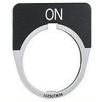
10250TM25
Description
Legend Plate
Manufacturer
EATON CUTLER HAMMER
Datasheet
1.10250T101.pdf
(244 pages)
Specifications of 10250TM25
Peak Reflow Compatible (260 C)
No
Leaded Process Compatible
No
For Use With
10250T Series Pushbutton Operators / Indicating Lights
Lead Free Status / RoHS Status
Contains lead / RoHS non-compliant


47-140
47
Joysticks (Continued)
Four-Position Joystick Operators
The joystick operated control unit is
intended for AC application only. For
other use, see Application Caution on
preceding page.
Table 47-222. 4-Position Joystick Operators — UL (NEMA) Type 3, 3R, 4, 4X, 12, 13
Field Conversion — Gate
The factory assembled 4-position
operator is assembled with a gate
arranged for four handle positions.
Figure 47-98. Handle Positions
Three additional gates, supplied with
every operator, allow on the job con-
version to 3- or 8-position operation as
illustrated below.
Figure 47-99. 2-, 3- or 8-Position Operation
Contact Block Limitations
4 Contact Blocks Max. —
2 in Each Position
2-Position
Momentary operators — spring return to center. For maintained operators add Suffix Code from Table 47-223.
Example: 10250T45110. Operator without latch, maintained in left and right positions.
or
Gate
Pushbuttons & Indicating Lights
30.5 mm Heavy-Duty Watertight/Oiltight
10250T Series, Joystick Components
4-Position
8-Position
or
Gate
Gate
3-Position
or
Gate
Description
Operator Only — AC Application Only
4-Position — without Latch
4-Position — with Latch
Hole Plug
To plug unused hole
or
The panel area required for the
4-position operator is equivalent to
two standard pushbutton operators.
Note: The latch holds the lever in the center
position. The trigger latch must be released
before lever can moved into any position.
The 8-position gate controls the four
functions shown as “Up,” “Down,”
“Left” and “Right.” The remaining
four diagonal positions each actuate
two adjacent functions (see Figure 47-
100); for example, “Left Down” actu-
ates both “Left” and “Down.” The
operator may be arranged for spring
return of handle to center position, or
maintained in up to eight positions
(see description of maintained posi-
tion operator).
Figure 47-100. Adjacent Functions
Maintained Position
For maintained position (non-spring
return), locate required maintained
position or positions of operating lever
in Table 47-223 and add appropriate
Suffix Number to the Catalog Number
selected from Table 47-222.
For more information visit: www.eaton.com
Left
Down
Left
Left
Catalog
Number
10250T451_
10250T461_
10250TA7
Up
Down
Up
Price
U.S. $
Down
Right
Right
Up
Right
Overall Dimensions in Inches (mm)
(47.8)
1.88
Table 47-223. Maintained Positions
Note: On an 8-position gate, when an
adjacent vertical and horizontal position
are both maintained, the included diagonal
position is also maintained.
Contact Blocks . . . . . . . . . . Page 47-148
Enclosures . . . . . . . . . . . . . Pages 47-153 – 47-154
Legend Plates. . . . . . . . . . . Pages 47-151 – 47-152
Discount Symbol . . . . . . . . 1CD1C
Maintained Positions
Up
X
—
—
—
X
X
X
—
—
—
X
X
X
—
X
4-Position Joystick
Operator
0.88 (22.4)
(101.6)
per Unit
4.0
Down
—
X
—
—
X
—
—
X
X
—
X
X
—
X
X
(30.2)
1.19
Left
—
—
X
—
—
X
—
X
—
X
X
—
X
X
X
4-Position Joystick
Operator with
Latch
Right
—
—
—
X
—
—
X
—
X
X
—
X
X
X
X
(95.3)
3.75
(31.8)
1.25
CA08102001E
Suffix
Number
10
11
12
13
14
15
March 2008
1
2
3
4
5
6
7
8
9
Related parts for 10250TM25
Image
Part Number
Description
Manufacturer
Datasheet
Request
R

Part Number:
Description:
10250T-E30-E34 PUSHBUTTON DISPLAY STAND
Manufacturer:
EATON CUTLER HAMMER
Part Number:
Description:
10250 STD. DUTY RECTANGULAR PB
Manufacturer:
EATON CUTLER HAMMER
Part Number:
Description:
10250 STD. DUTY RECTANGULAR PB
Manufacturer:
EATON CUTLER HAMMER
Part Number:
Description:
Handle Tie Bar For (2) - 1 Pole Type BR Breakers
Manufacturer:
EATON CUTLER HAMMER
Part Number:
Description:
Type CL Breaker 25A/1Pole 120/240V 10K-Classified 1" Ckt Bkr
Manufacturer:
EATON CUTLER HAMMER