704.962.5 EAO, 704.962.5 Datasheet - Page 13
704.962.5
Manufacturer Part Number
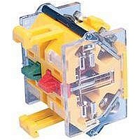
704.962.5
Description
Switch Legend Plate
Manufacturer
EAO
Datasheet
1.704-1140.pdf
(21 pages)
Specifications of 704.962.5
Label Size
42 X 42mm
Label Type
Self Adhesive
Legend
Blank
Background Color
Natural
For Use With
04 Series Emergency Stop Pushbuttons
Lead Free Status / RoHS Status
Lead free / RoHS Compliant


Series 04
Slow-make switching element
Switching system
The double-break, slow-make switching element is equipped with one
or two independent contact systems, acting as normally open or
normally closed contact. The normally closed contact has forced
opening.
Slow-make contacts with forced action are ideal for high switch
ratings.
Up to 3 switching elements can be snapped to each actuator.
For the emergency-stop pushbutton use the slow-make switching
element (max. 2).
Material
Material of contact
Hard Silver, Gold/Silver, Silver/Palladium (for aggressive atmospheres)
Switch housing
Polycarbonate (PC)
Mechanical characteristics
Terminals
Screw terminals
Plug-in terminals 6.3 x 0.8 mm
max. wire cross-section 2 x 2.5 mm²
max. wire cross-section of stranded cable 2 x 1.5 mm²
For switches with plug-in terminals it is necessary to provide insulation
sleeves and to maintain a spacing of 65 mm between rows (mounting
dimensions)
Tightening torque
Screws at the mounting flange max. 25 Ncm
Screws at switching element max. 50 Ncm
Actuating force
1 Normally closed 2 N
1 Normally open 3.1 N
Actuating travel
5.8 mm ±0.2 mm
Rebound time
≤1 ms
Mechanical lifetime
(with 1 switching element)
Pushbutton, maintained action
Pushbutton momentary action
Selector switch maintained action
Selector switch momentary action
Emergency-stop switch
Keylock switch maintained action
Keylock switch momentary action
Electrical characteristics
Standards
The switches comply with the „Standards for low-voltage switching
devices“ EN IEC 60947-5-1
Rated Insulation Voltage Ui
500 VAC/600 VDC, as per EN IEC 60947-5-1
Contact resistance
New state ≤50 mΩ as per DIN IEC 60512-2-4
Isolation resistance
≥10 MΩ between open contacts at 500 VDC, as per
DIN IEC 60512-2-10
1.5 million
3 million
1.25 million
2.5 million
50 000
25 000
50 000
Cycles of operation
Cycles of operation
Cycles of operation
Cycles of operation
Cycles of operation
Cycles of operation
Cycles of operation
Conventional free air thermal current Ith
10 A, as per EN IEC 60947-5-1
the maximum current in continuous operation and at ambient
temperature must not exceed the quoted maximum values.
Switch rating
At switch rating AC for Gold/Silver, Silver/Palladium and Hard Silver
contacts service category AC-15, as per EN IEC 60947-5-1 (cosφ 0.3)
Voltage
Current
At switch rating DC for Gold-, Silver- and Hard Silver contacts service
category DC-13, as per EN IEC 60947-5-1
Voltage
Current
Recommended minimum operational data
Gold/Silver contacts:
Voltage
Current
Hard Silver contacts:
Voltage
Current
Protection class
Indicators and switches, fit for mounting into devices with protection
class II
Environmental conditions
Storage temperature
−40 °C ... +85 °C
Operating temperature
−40 °C ... +55 °C
Shock resistance
(single impacts, semi-sinusoidal)
300 m/s² puls width 11 ms, as per EN IEC 60068-2-27
Vibration resistance
(sinusoidal)
100 m/s² at 10 Hz ... 500 Hz, amplitude 0.75 mm, as per
EN IEC 60068-2-6
Approvals
Approbations
CB (IEC 60947)
CCC
CSA
Germanischer Lloyd
GOST
SEV
UL
Declaration of conformity
CE
NF F16-102
230 VAC
7 A
24 VDC
10 A
24 VDC
10 mA
24 VDC
50 mA
400 VAC
5 A
60 VDC
5 A
110 VDC
2 mA
110 VDC
10 mA
Technical Data
500 VAC
4 A
110 VDC
2.5 A
250 VDC
0.6 A
26
Related parts for 704.962.5
Image
Part Number
Description
Manufacturer
Datasheet
Request
R

Part Number:
Description:
Indicator
Manufacturer:
EAO
Datasheet:


Part Number:
Description:
Switch Actuator
Manufacturer:
EAO
Datasheet:

Part Number:
Description:
Switch Actuator
Manufacturer:
EAO
Datasheet:
Part Number:
Description:
Switch Actuator
Manufacturer:
EAO
Datasheet:
Part Number:
Description:
Switch Actuator
Manufacturer:
EAO
Datasheet:


Part Number:
Description:
SINGLE CHIP LED/ T1 BI-PIN/ 2.1VDC/20MA - RED
Manufacturer:
EAO
Datasheet:

Part Number:
Description:
INDICATOR, INCAND LAMP, BI PIN
Manufacturer:
EAO
Datasheet:

Part Number:
Description:
INDICATOR, BI-PIN
Manufacturer:
EAO
Datasheet:

Part Number:
Description:
INDICATOR, INCAND LAMP, MIDGET GROOVED
Manufacturer:
EAO
Datasheet: