D6F-P0010A1 Omron, D6F-P0010A1 Datasheet - Page 5
D6F-P0010A1
Manufacturer Part Number
D6F-P0010A1
Description
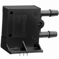
SENSOR AIRFLOW 0-50KPA PCB TERM
Manufacturer
Omron
Series
D6Fr
Type
MEMS Flow Sensorr
Specifications of D6F-P0010A1
Supply Voltage
5 VDC to 10 VDC
Sensing Range
0 ~ 1 LPM
Flow Sensor Type
Air
Voltage - Input
4.75 V ~ 9.45 V
Material - Body
PBT Plastic
Sensor Type
MEMS Flow Sensor
Rated Range
1 L/min
Pressure Max
7psi
Supply Voltage Range Dc
4.75V To 5.25V
Accuracy
± 5%
Sensing Accuracy
5%
Output Voltage Max
2.5V
Flow Rate Min
0l/min
No. Of Ports
2
Sensor Terminals
PCB
Function
AirFlow
Mounting Type
PCB
Output
Voltage
Primary Type
AirFlow
Range, Measurement
1 Liter/Min.
Technology
MEMS
Termination
Solder
Voltage, Supply
10 VDC
Voltage, Switching
4 VDC
Flow Rate Max
1l/min
Rohs Compliant
Yes
Accuracy %
5%
Lead Free Status / RoHS Status
Lead free / RoHS Compliant
Port Size
-
Switch Function/rating
-
Lead Free Status / Rohs Status
Lead free / RoHS Compliant
Other names
D6FP0010A1
Z2785
Z2785


D6F-P
Safety Precautions
The D6F is built for use with general-purpose devices. In particu-
lar, when using the D6F for applications with the safety require-
ments described below, take steps to ensure system and device
safety through measures such as fail-safe designs, redundant
designs, and regular inspections. The D6F-P is not suitable for: or
if that is too strong of a statement, something like:
"Particular attention should be paid to applications including, but
not limited to, the following:
• Safety devices for ensuring safety for persons.
• Transportation equipment control (such as applications to stop
• Aviation and space equipment
• Nuclear power equipment
Do not use the D6F for applications in which D6F operation would
directly affect human life.
Fluids, Piping, and Sensor Installation
<D6F-0010A1/-P0010A2>
<D6F-0010AM2>
operation)
1. Do not use combustible gas (such as hydrogen) or corro-
2. The specified performance may not be obtained if the D6F
3. After removing the Sensor from the package, do not allow
4. It is recommended that the pipes be mounted horizontally.
5. Install the Sensor on a flat surface. Incorrect installation
6. Turn OFF the power supply to the system before installing
7. Always check operation after installing the Sensor.
8. Do not drop the Sensor or disassemble the cover.
9. Depending on the environment and the mounting position,
10.Install the piping so that the fluid flows in the direction from
1. When installing the Sensor on a PCB, solder the terminals
2. Install the Sensor using M2.6 panhead screws or tapping
1. Install the Sensor using M3 panhead screws or tapping
2. Use O-rings to seal the fluid inlet and outlet sections. (Rec-
Caution
Precautions for Correct Use
sive gas (such as chlorine, sulfur, acid, or alkali) other than
the specified applicable fluids. Doing so may cause product
failure.
is used for fluids other than the specified applicable fluids.
foreign particles to enter the piping. Foreign particles in the
piping may cause product failure.
If they are not mounted horizontally, an error of ±1% FS or
higher may result.
may cause malfunctions or may make it impossible to
obtain correct measurements.
the Sensor. If the Sensor is installed while the power supply
is ON, electric shock or incorrect operation may occur.
foreign objects, such as dust or dirt, may enter into the Sen-
sor and partially or completely block the flow path. If this
occurs, the Sensor may not be able to sufficiently perform
as described above. Make sure that you understand how to
use the Sensor and test it in advance with the actual equip-
ment with which it is to be used.
plus (+) to minus (-). Correct measurements cannot be
obtained if the fluid flows in the wrong direction.
after first securing the Sensor to the PCB.
screws of the same diameter, and tighten them to a torque
of 0.59 N•m maximum.
screws of the same diameter, and tighten them to a torque
of 0.59 N•m maximum.
ommended O-ring: JIS B 2401 bearing number P4 or ISO
3601-1 Dicignation: A0037G)
Operating Environment
Do not use the Sensor in the following locations:
Countermeasures Against Noise
Noise may make it impossible to obtain correct measurements.
Consider the following countermeasures.
Power Supply
• Use the applicable connectors. Directly soldering the connec-
• Check the terminal names and polarity and wire the power sup-
• When using a commercially available switching regulator,
The RoHS mark is displayed on the packing of products for which
the six substances banned by the RoHS Directive have been
abolished (both in processing and in the electronic components
mounted to the PCBs).
Note:
RoHS Compliance Standards
The following standards are used to determine RoHS compliance
for the six banned substances.
• Locations subject to direct radiant heat from heating equipment
• Locations subject to water or oil
• Locations subject to direct sunlight
• Locations subject to sudden temperature changes
• Locations where there is a possibility of icing or condensation
• Locations subject to strong vibration or shock
• Install the Sensor as far as possible from devices that gener-
• Attach surge absorbers or noise filters to noise-generating
tion terminals will cause product failure.
ply correctly. Incorrect wiring will cause failure of internal com-
ponents.
ground the FG (frame ground) and G (ground) terminals.
• Lead: 1,000 ppm max.
• Hexavalent chromium: 1,000 ppm max.
• Mercury: 1,000 ppm max.
• PBB: 1,000 ppm max.
• Cadmium: 100 ppm max.
• PBDE: 1,000 ppm max.
Installation Example
O-rings are not attached.
RoHS Directive
ate surges or strong high frequencies (such as high-fre-
quency welders and machines).
devices that are near the Sensor (in particular, equipment
with inductance, such as motors, transformers, solenoids,
and magnetic coils). (It also helps to separate pipes and
ducts, and to use shielded cables.)
RoHS marking may be deleted if it is later determined that
parts that were previously treated as RoHS compliant are
not compliant due to circumstances at the supplier of the
parts.
O-ring
M3 panhead screw or tapping
screw of the same diameter
D6F-P
5
Related parts for D6F-P0010A1
Image
Part Number
Description
Manufacturer
Datasheet
Request
R

Part Number:
Description:
AIRFLOW SENSOR MEMS 20L/MIN
Manufacturer:
Omron
Datasheet:

Part Number:
Description:
Sensor Cable Assembly
Manufacturer:
Omron
Datasheet:

Part Number:
Description:
SENSOR AIRFLOW 0-50KPA W/CONN
Manufacturer:
Omron
Datasheet:

Part Number:
Description:
AIRFLOW SENSOR 0-3 M/SEC 3.3V
Manufacturer:
Omron
Datasheet:

Part Number:
Description:
AIRFLOW SENSOR 0-4 M/SEC 12/24V
Manufacturer:
Omron
Datasheet:

Part Number:
Description:
AIRFLOW SENSOR 0-1 M/SEC 12/24V
Manufacturer:
Omron
Datasheet:

Part Number:
Description:
SENSOR AIR FLOW TYPE 0-2LTR METL
Manufacturer:
Omron
Datasheet:

Part Number:
Description:
SENSOR AIRFLOW MANFLD MNT 12/24V
Manufacturer:
Omron
Datasheet:

Part Number:
Description:
SENSOR AIRFLOW MNT 12/24V
Manufacturer:
Omron
Datasheet:

Part Number:
Description:
SENSOR AIR FLOW TYPE 0-1LTR PLST
Manufacturer:
Omron
Datasheet:

Part Number:
Description:
Micro-Flow Sensor
Manufacturer:
Omron
Datasheet:

Part Number:
Description:
Micro-Flow Sensor
Manufacturer:
Omron
Datasheet:

Part Number:
Description:
Micro-Flow Sensor
Manufacturer:
Omron
Datasheet:

Part Number:
Description:
Micro Flow Sensor
Manufacturer:
Omron
Datasheet:

Part Number:
Description:
G6S-2GLow Signal Relay
Manufacturer:
Omron Corporation
Datasheet: