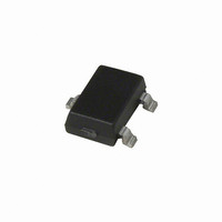
A3213ELHLT-T Allegro Microsystems Inc, A3213ELHLT-T Datasheet - Page 10

A3213ELHLT-T
Manufacturer Part Number
A3213ELHLT-T
Description
IC SWITCH HALL EFFECT SOT23W
Manufacturer
Allegro Microsystems Inc
Type
Omnipolar Switchr
Datasheet
1.A3213ELHLT-T.pdf
(13 pages)
Specifications of A3213ELHLT-T
Sensing Range
±70G Trip, ±10G Release
Voltage - Supply
2.4 V ~ 5.5 V
Current - Supply
2mA
Current - Output (max)
1mA
Output Type
Digital, Open Collector
Features
Ultra Sensitive
Operating Temperature
-40°C ~ 85°C
Package / Case
SOT-23W
Peak Reflow Compatible (260 C)
Yes
Termination Type
SMD
Output Current
1mA
Supply Voltage Max
5.5V
Leaded Process Compatible
Yes
No. Of Pins
3
Hall Effect Type
Switch
Supply Voltage Min
2.4V
Magnetic Type
Latch
Operating Supply Voltage (min)
2.4V
Operating Supply Voltage (typ)
3V
Operating Supply Voltage (max)
5.5V
Mag Sensor Operate Point (g)
70Gs
Mag Sensor Release Point (g)
10Gs
Mag Sensor Hysteresis(g)
10Gs
Package Type
SOT-23W
Pin Count
3
Mounting
Surface Mount
Operating Temp Range
-40C to 85C
Operating Temperature Classification
Industrial
Filter Terminals
SMD
Rohs Compliant
Yes
Lead Free Status / RoHS Status
Lead free / RoHS Compliant
Lead Free Status / RoHS Status
Lead free / RoHS Compliant, Lead free / RoHS Compliant
Other names
620-1041-2
Available stocks
Company
Part Number
Manufacturer
Quantity
Price
Company:
Part Number:
A3213ELHLT-T
Manufacturer:
ALLEGRO
Quantity:
36 000
A3213
A3214
and
A Terminal #1 mark area
B Exposed thermal pad (reference only, terminal #1
C Reference land pattern layout (reference IPC7351);
3X
2.00 ±0.15
0.40 ±0.05
For Reference Only, not for tooling use (reference DWG-2865;
reference JEDEC MO-229UCCD)
Dimensions in millimeters
Exact case and lead configuration at supplier discretion within limits shown
identifier appearance at supplier discretion)
All pads a minimum of 0.20 mm from all adjacent pads; adjust as
necessary to meet application process requirements and PCB layout
tolerances; when mounting on a multilayer PCB, thermal vias at the
exposed thermal pad land can improve thermal dissipation (reference
EIA/JEDEC Standard JESD51-5)
0.08
D
C
0.25
E
+0.07
–0.05
Micropower Ultra-Sensitive Hall-Effect Switches
1
1
A
1.25
B
2.00 ±0.15
1.00 BSC
Package EL, 3-Contact MLP/DFN
+0.10
–0.15
3
3
1.12
E
2
2
0.325
0.50 ±0.05
0.78
E
0.138
0.925
+0.050
–0.150
SEATING
PLANE
E
G
D Coplanarity includes exposed thermal pad and terminals
F
C
Hall Element (not to scale)
Active Area Depth, 0.18 mm NOM
Branding scale and appearance at supplier discretion
F
2.40
G
W = Week of manufacture
Y = Last two digits of year of manufacture
N = Last two digits of device part number
Standard Branding Reference View
0.30
0.925
0.65
C
0.30
PCB Layout Reference View
1
1
YWW
NN
1.250
115 Northeast Cutoff
1.508.853.5000; www.allegromicro.com
Allegro MicroSystems, Inc.
Worcester, Massachusetts 01615-0036 U.S.A.
3
0.50
0.325
0.138
10


