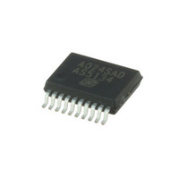
AS5134-ZSST austriamicrosystems, AS5134-ZSST Datasheet - Page 22

AS5134-ZSST
Manufacturer Part Number
AS5134-ZSST
Description
IC ENCODER PROG 20-SSOP
Manufacturer
austriamicrosystems
Type
Linear, Rotary Encoder - Programmabler
Datasheet
1.AS5134_PB.pdf
(40 pages)
Specifications of AS5134-ZSST
Sensing Range
20mT ~ 80mT
Voltage - Supply
4.5 V ~ 5.5 V
Current - Supply
15mA
Output Type
Digital, PWM
Features
Programmable
Operating Temperature
-40°C ~ 140°C
Package / Case
20-SSOP
Lead Free Status / RoHS Status
Lead free / RoHS Compliant
Current - Output (max)
-
Other names
AS5134-ZSSTTR
Available stocks
Company
Part Number
Manufacturer
Quantity
Price
Company:
Part Number:
AS5134-ZSST
Manufacturer:
ICT
Quantity:
1 200
AS5134
Data Sheet - A p p l i c a t i o n I n f o r m a t i o n
8 Application Information
The benefits of AS5134 are as follows:
8.1 AS5134 Programming
The AS5134 offers the following user programmable options:
position. This useful feature simplifies the assembly process as the magnet does not need to be mechanically adjusted to the electrical zero
position. It can be assembled in any rotation angle and later matched to the mechanical zero position by zero position programming. The 8,5-bit
user programmable zero position can be applied both temporarily (command WRITE OTP, #31) or permanently (command PROG OTP, #25).
magnetic field range of the AS5134 by setting the sensitivity level. The 2-bit user programmable sensitivity setting can be applied both
temporarily (command WRITE OTP, #31) or permanently (command PROG OTP, #25).
frozen and the power consumption is reduced to typ. 1.5 mA. Start-up from this mode to normal operation can be accomplished within 250µs.
This mode is recommended for applications, where low power, but fast start-up and short reading cycle intervals are required.
8.1.1 OTP Programming Connection
Programming of the AS5134 OTP memory does not require a dedicated programming hardware. The programming can be simply accomplished
over the serial 3-wire interface
OTP, #25), a constant DC voltage of 8.0 – 8.5V (=100mA) must be connected to pin 1 (PROG). For temporary OTP write (“soft write”; command
WRITE OTP, #31), the programming voltage is not required. The capacitors must be as close as possible to the pin, to ensure that a serial
inductance of 50nH is not to be exceeded. The 50nH inductance could translate into a cable length of approximately 5cm.
Figure 14. OTP Programming Connection
www.austriamicrosystems.com/AS5134
Complete system-on-chip, no angle calibration required
Flexible system solution provides absolute serial, ABI, UVW and PWM outputs
Ideal for applications in harsh environments due to magnetic sensing principle
High reliability due to non-contact sensing
Robust system, tolerant to horizontal misalignment, airgap variations, temperature variations and external magnetic fields
Zero Position Programming.
Magnetic Field Optimization.
Low Power Mode.
Low Power Mode is a power saving mode with fast start-up. In Low Power Mode, all internal digital registers are
(see Figure 15)
VSS
VDD
+5V
This programming option allows the user to program any rotation angle of the magnet as the new zero
This programming option allows the user to match the vertical distance of the magnet with the optimum
VDD
VSS
or the optional 2-wire interface
Output
Output
I/O
8.0 – 8.5V
+
-
Revision 1.13
(see Figure
CS
DCLK
DIO
PROG
VDD
6). For permanent programming (command PROG
C2
VSS
100nF
22 - 40


