A3290KUA-T Allegro Microsystems Inc, A3290KUA-T Datasheet - Page 6
A3290KUA-T
Manufacturer Part Number
A3290KUA-T
Description
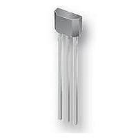
IC HALL EFFECT LATCH 3-SIP
Manufacturer
Allegro Microsystems Inc
Type
Bipolar Latchr
Specifications of A3290KUA-T
Package / Case
3-SIP
Sensing Range
50G Trip, -50G Release
Voltage - Supply
4.2 V ~ 24 V
Current - Supply
8mA
Current - Output (max)
25mA
Output Type
Digital, Open Drain
Features
Regulated Voltage
Operating Temperature
-40°C ~ 125°C
Hall Effect Type
Latch
Output Current
25mA
Sensor Case Style
SIP
No. Of Pins
3
Supply Voltage Range
4.2V To 24V
Operating Temperature Range
-40°C To +125°C
Bandwidth
800kHz
Svhc
No SVHC (15-Dec-2010)
Rohs Compliant
Yes
Lead Free Status / RoHS Status
Lead free / RoHS Compliant


A3290
A3291
Note that these devices latch; that is, after a south (+) polarity
magnetic field of sufficient strength impinging on the branded
face of the device turns on the device, the device remains on until
the magnetic field is reduced below the Release Point threshold,
B
The difference in the magnetic operate and release points is the
hysteresis, B
It is strongly recommended that an external bypass capacitor be
connected (in close proximity to the Hall element) between the
supply and ground of the device to reduce both external noise
and noise generated by the chopper-stabilization technique. This
configuration is shown in figure 4.
The simplest form of magnet that will operate these devices is a
ring magnet.Other methods of operation, such as linear magnets,
are possible.
The device must be operated below the maximum junction
temperature of the device, T
peak conditions, reliable operation may require derating supplied
power or improving the heat dissipation properties of the applica-
tion. The Package Thermal Resistance, R
summarizing the ability of the application and the device to dissi-
RP
. At that transition, the device output goes high (turns off).
HYS
and
, of the device. This built-in hysteresis allows
J(max)
. Under certain combinations of
Chopper Stabilized, Precision Hall Effect Latches
Figure 4. Typical basic application circuit. A bypass capacitor is highly
recommended.
JA
, is a figure of merit
for Consumer and Industrial Applications
Application Information
0.1 uF
VCC
mechanical vibration and electrical noise.
When the devices are powered on, if the ambient magnetic field
has an intensity that is between B
state is indeterminate. The first time that the level of B either
rises through B
output state is obatined.
pate heat from the junction (die), through all paths to the ambient
air. Its primary component is the Effective Thermal Conductivity,
K, of the printed circuit board, including adjacent devices and
traces. Radiation from the die through the device case, R
relatively small component of R
T
overmolding. Sample power dissipation results are given in the
Thermal Characteristics section. Additional thermal data is also
available on the Allegro website.
Extensive applications information for Hall-effect devices is
available in: Hall-Effect IC Applications Guide, Application Note
27701 and Guidelines for Designing Subassemblies Using Hall-
Effect Devices, Application Note 27703.1
clean switching of the output, even in the presence of external
A
A329x
, and air motion are significant external factors, damped by
GND
VOUT
OP
, or falls through B
V
CC
115 Northeast Cutoff
1.508.853.5000; www.allegromicro.com
Allegro MicroSystems, Inc.
Worcester, Massachusetts 01615-0036 U.S.A.
JA
OP
. Ambient air temperature,
and B
RP
, however, the correct
RP
, the initial output
JC
, is
6
Related parts for A3290KUA-T
Image
Part Number
Description
Manufacturer
Datasheet
Request
R

Part Number:
Description:
SOCKET ADPTR PLCC/84PIN .600 DIP
Manufacturer:
Aries Electronics
Datasheet:

Part Number:
Description:
IC, HALL EFFECT SENSOR, Linear, SOIC-8
Manufacturer:
Allegro Microsystems Inc
Datasheet:
Part Number:
Description:
IC, HALL EFFECT SENSOR, Linear, SOIC-8
Manufacturer:
Allegro Microsystems Inc
Datasheet:
Part Number:
Description:
IC, HALL EFFECT SENSOR, Linear, SOIC-8
Manufacturer:
Allegro Microsystems Inc
Datasheet:

Part Number:
Description:
IC SWITCH INTERFACE 2CHAN 8-SOIC
Manufacturer:
Allegro Microsystems Inc
Datasheet:

Part Number:
Description:
IC SMOKE DETECTOR ION 16-DIP
Manufacturer:
Allegro Microsystems Inc
Datasheet:
Part Number:
Description:
IC SMOKE DETECTOR ION 16-DIP
Manufacturer:
Allegro Microsystems Inc
Datasheet:
Part Number:
Description:
IC SMOKE DETECTOR ION 16-DIP
Manufacturer:
Allegro Microsystems Inc
Datasheet:
Part Number:
Description:
IC SMOKE DETECTOR PHOTO 16-DIP
Manufacturer:
Allegro Microsystems Inc
Datasheet:
Part Number:
Description:
IC SMOKE DETECTOR ION 16-DIP
Manufacturer:
Allegro Microsystems Inc
Datasheet:
Part Number:
Description:
IC SMOKE DETECTOR PHOTO 16-DIP
Manufacturer:
Allegro Microsystems Inc
Datasheet:
Part Number:
Description:
IC SMOKE DETECTOR PHOTO 16-DIP
Manufacturer:
Allegro Microsystems Inc
Datasheet:
Part Number:
Description:
IC SMOKE DETECTOR ION 16-DIP
Manufacturer:
Allegro Microsystems Inc
Datasheet:
Part Number:
Description:
IC SMOKE DETECTOR PHOTO 16-SOIC
Manufacturer:
Allegro Microsystems Inc
Datasheet:

Part Number:
Description:
IC LED DRIVER HIGH BRIGHT 16-QFN
Manufacturer:
Allegro Microsystems Inc
Datasheet: