A1301EUA-T Allegro Microsystems Inc, A1301EUA-T Datasheet

IC SENSOR HALL EFFECT 3-SIP

A1301EUA-T

Manufacturer Part Number
A1301EUA-T
Description
IC SENSOR HALL EFFECT 3-SIP
Manufacturer
Allegro Microsystems Inc
Type
Linear - Ratiometricr
Datasheets

Specifications of A1301EUA-T

Sensing Range
1.8mV/G ~ 3.2mV/G
Voltage - Supply
4.5 V ~ 6 V
Current - Supply
11mA
Current - Output (max)
10mA
Output Type
Digital, Open Drain
Operating Temperature
-40°C ~ 85°C
Package / Case
3-SIP
Hall Effect Type
Linear
Output Current
10mA
Sensor Case Style
SIP
No. Of Pins
3
Supply Voltage Range
4.5V To 6V
Operating Temperature Range
-40°C To +85°C
Operating Temperature Max
85°C
Operating Supply Voltage (min)
4.5V
Operating Supply Voltage (typ)
5V
Operating Supply Voltage (max)
6V
Package Type
Ultra Mini SIP
Pin Count
3
Mounting
Through Hole
Operating Temp Range
-40C to 85C
Operating Temperature Classification
Industrial
Svhc
No SVHC (15-Dec-2010)
Rohs Compliant
Yes
Filter Terminals
SIP
Lead Free Status / RoHS Status
Lead free / RoHS Compliant
Features
-
Lead Free Status / Rohs Status
Compliant
Features and Benefits
▪ Low-noise output
▪ Fast power-on time
▪ Ratiometric rail-to-rail output
▪ 4.5 to 6.0 V operation
▪ Solid-state reliability
▪ Factory-programmed at end-of-line for optimum
▪ Robust ESD performance
Packages: 3 pin SOT23W (suffix LH), and
3 pin SIP (suffix UA)
Not to scale
A1301-DS, Rev. 17
performance
Continuous-Time Ratiometric Linear Hall Effect Sensor ICs
V+
C BYPASS
VC
C
Functional Block Diagram
To all subcircuits
GND
Amp
Gain
Description
The A1301 and A1302 are continuous-time, ratiometric, linear
Hall-effect sensor ICs. They are optimized to accurately provide
a voltage output that is proportional to an applied magnetic
field. These devices have a quiescent output voltage that is
50% of the supply voltage. Two output sensitivity options
are provided: 2.5 mV/G typical for the A1301, and 1.3 mV/G
typical for the A1302.
The Hall-effect integrated circuit included in each device
includes a Hall circuit, a linear amplifier, and a CMOS Class A
output structure. Integrating the Hall circuit and the amplifier
on a single chip minimizes many of the problems normally
associated with low voltage level analog signals.
High precision in output levels is obtained by internal gain
and offset trim adjustments made at end-of-line during the
manufacturing process.
These features make the A1301 and A1302 ideal for use in
position sensing systems, for both linear target motion and
rotational target motion. They are well-suited for industrial
applications over extended temperature ranges, from –40°C
to 125°C.
Two device package types are available: LH, a 3-pin SOT23W
type for surface mount, and UA, a 3-pin ultramini SIP for
through-hole mount. They are lead (Pb) free (suffix, –T) with
100% matte tin plated leadframes.
Control
Offset
Out
A1301 and A1302
Trim
VOUT

Related parts for A1301EUA-T

A1301EUA-T Summary of contents

Page 1

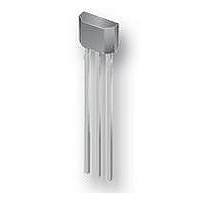
Continuous-Time Ratiometric Linear Hall Effect Sensor ICs Features and Benefits ▪ Low-noise output ▪ Fast power-on time ▪ Ratiometric rail-to-rail output ▪ 4.5 to 6.0 V operation ▪ Solid-state reliability ▪ Factory-programmed at end-of-line for optimum performance ▪ Robust ESD ...

Page 2

... A1301 and A1302 Selection Guide Part Number Packing* A1301EUA-T Bulk, 500 pieces/bag A1301KLHLT-T 7-in. tape and reel, 3000 pieces/reel A1301KUA-T Bulk, 500 pieces/bag A1302ELHLT-T 7-in. tape and reel, 3000 pieces/reel A1302KLHLT-T 7-in. tape and reel, 3000 pieces/reel A1302KUA-T Bulk, 500 pieces/bag *Contact Allegro for additional packing options ...

Page 3

A1301 and A1302 Package Terminal List Symbol Package LH VCC VOUT GND Continuous-Time Ratiometric Linear Hall Effect Sensor ICs Pin-out Drawings 2 Number Package Connects power supply to chip 2 3 Output from circuit ...

Page 4

A1301 and A1302 DEVICE CHARACTERISTICS over operating temperature range, T Characteristic Electrical Characteristics Supply Voltage Supply Current V Output Voltage V Output Bandwidth Power-On Time Output Resistance Wide Band Output Noise, rms Ratiometry Quiescent Output Voltage Error ΔV 1 with ...

Page 5

A1301 and A1302 Quiescent Output Voltage. In the quiescent state (no sig- nificant magnetic field 0), the output, V half of the supply voltage throughout the entire operating CC ranges of V and ambient temperature, T ...

Page 6

A1301 and A1302 1301 Device Sensitivity vs. Ambient Temperature 2.65 2.60 UA Package 2.55 2.50 LH Package 2.45 2.40 2.35 –50 – Temperature (°C) 1301 Device V vs. Ambient Temperature OUTQ 2.60 2.55 2.50 2.45 2.40 –50 ...

Page 7

A1301 and A1302 1301 Device V OUTQ 3.5 3.0 2.5 2.0 1.5 4.5 5.0 Supply Voltage (V) 1301 Device LIN+ and LIN– vs. Supply Voltage 100.4 100.3 LIN– 100.2 100.1 100.0 LIN+ 99.9 99.8 4.5 5.0 Supply Voltage (V) 1301 ...

Page 8

A1301 and A1302 +0.12 2.98 –0.08 3 +0.10 2.90 –0. 10° REF 0.95 BSC For Reference Only; not for tooling use (reference dwg. 802840) Dimensions in millimeters Dimensions exclusive of mold flash, gate burrs, and dambar protrusions Exact ...

Page 9

A1301 and A1302 4.09 45° +0.08 3.02 –0.05 1.02 MAX 0.51 REF 1 14.99 ±0.25 +0.05 0.43 –0.07 Please note that there are changes to the existing UA package drawing pending. Please contact the Allegro Marketing department for additional information. ...

Page 10

A1301 and A1302 4.09 45° +0.08 3.02 –0.05 2.16 MAX 0.51 REF 1 15.75 ±0.51 +0.05 0.43 –0.07 Copyright ©2005-2010, Allegro MicroSystems, Inc. Allegro MicroSystems, Inc. reserves the right to make, from time to time, such de par tures from ...

Related keywords