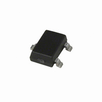
A1101ELHLT-T Allegro Microsystems Inc, A1101ELHLT-T Datasheet - Page 8

A1101ELHLT-T
Manufacturer Part Number
A1101ELHLT-T
Description
IC SWITCH HALL EFFECT SOT-23W
Manufacturer
Allegro Microsystems Inc
Type
Unipolar Switchr
Datasheet
1.A1101ELHLT-T.pdf
(11 pages)
Specifications of A1101ELHLT-T
Sensing Range
175G Trip, 10G Release
Voltage - Supply
3.8 V ~ 24 V
Current - Supply
7.5mA
Current - Output (max)
25mA
Output Type
Digital, Open Collector
Features
Regulated Voltage
Operating Temperature
-40°C ~ 85°C
Package / Case
SOT-23W
Operate Point Typ
100G
Termination Type
SMD
No. Of Pins
3
Hall Effect Type
Switch
Supply Voltage Min
3.8V
Release Point Min
10G
Peak Reflow Compatible (260 C)
Yes
Output Current
20mA
Magnetic Type
Unipolar
Operating Supply Voltage (min)
3.8V
Operating Supply Voltage (typ)
5/9/12/15/18V
Operating Supply Voltage (max)
24V
Mag Sensor Operate Point (g)
160Gs
Mag Sensor Release Point (g)
10Gs
Mag Sensor Hysteresis(g)
55Gs
Package Type
SOT-23W
Pin Count
3
Mounting
Surface Mount
Operating Temp Range
-40C to 85C
Operating Temperature Classification
Industrial
Filter Terminals
SMD
Rohs Compliant
Yes
Leaded Process Compatible
Yes
Operate Point Max
175G
Lead Free Status / RoHS Status
Lead free / RoHS Compliant
Lead Free Status / RoHS Status
Lead free / RoHS Compliant, Lead free / RoHS Compliant
Available stocks
Company
Part Number
Manufacturer
Quantity
Price
Company:
Part Number:
A1101ELHLT-T
Manufacturer:
BSI
Quantity:
1 001
A1101, A1102, A1103,
A1104, and A1106
ADDITIONAL APPLICATIONS INFORMATION
Extensive applications information for Hall-effect devices is
available in:
• Hall-Effect IC Applications Guide, Application Note 27701
• Hall-Effect Devices: Gluing, Potting, Encapsulating, Lead
Welding and Lead Forming, Application Note 27703.1
• Soldering Methods for Allegro’s Products – SMT and Through-
Hole, Application Note 26009
All are provided in Allegro Electronic Data Book, AMS-702,
and the Allegro Web site, www.allegromicro.com.
Figure 2. Continuous-Time Application, B < B
Position 1, power is applied to the device. Position 2, the output assumes the correct state at a time prior to the maximum Power-On Time, t
The case shown is where the correct output state is HIGH . Position 3, t
valid, a control unit reads the output. Position 5, power is removed from the device.
V
V
OUT
CC
1
RP
.. This figure illustrates the use of a quick cycle for chopping V
2
t
PO(max)
PO(max)
3
Continuous-Time Switch Family
has elapsed. The device output is valid. Position 4, after the output is
Output Sampled
4
5
115 Northeast Cutoff
1.508.853.5000; www.allegromicro.com
Allegro MicroSystems, Inc.
Worcester, Massachusetts 01615-0036 U.S.A.
CC
in order to conserve battery power.
t
t
PO(max)
.
8


