A1147LLHLT Allegro Microsystems Inc, A1147LLHLT Datasheet
A1147LLHLT
Specifications of A1147LLHLT


Related parts for A1147LLHLT


A1147LLHLT Summary of contents
Page 1
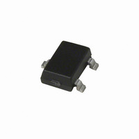
Low Current Ultrasensitive Two-Wire Chopper-Stabilized These parts are in production but have been determined to be NOT FOR NEW DESIGN. This classification indicates that sale of this device is currently restricted to existing customer applications. The device should not be ...
Page 2
Low Current Ultrasensitive Two-Wire Chopper-Stabilized Features and Benefits ▪ Chopper stabilization ▫ Low switchpoint drift over operating temperature range ▫ Low sensitivity to stress ▪ Factory programmed at end-of-line for optimized switchpoints ▪ On-chip protection ▫ Supply transient protection ▫ ...
Page 3
... LOW in the presence of a south-polarity magnetic Part Number Pb-Free A1147ELHLT-T Yes Tape and Reel, 3000 pieces/reel A1147EUA-T Yes Bulk Bag, 500 pieces/bag A1147LLHLT-T Yes Tape and Reel, 3000 pieces/reel A1147LUA-T Yes Bulk Bag, 500 pieces/bag A1148ELHLT-T Yes Tape and Reel, 3000 pieces/reel ...
Page 4
A1147 and A1148 Chopper-Stabilized Unipolar Hall Effect Switches ELECTRICAL CHARACTERISTICS Characteristic Symbol Supply Voltage 1 2 Supply Current Reverse Supply Current Supply Zener Clamp Voltage V ZSUPPLY 3 Supply Zener Clamp Current I ZSUPPLY Output Slew Rate 4 Chopping Frequency ...
Page 5
A1147 and A1148 Chopper-Stabilized Unipolar Hall Effect Switches Supply Current (Low) versus Ambient Temperature at Various Levels of V (A1147 and A1148 – 100 Ambient Temperature, T Operate Point versus Ambient Temperature ...
Page 6
A1147 and A1148 Chopper-Stabilized Unipolar Hall Effect Switches THERMAL CHARACTERISTICS may require derating at maximum conditions, see application information Characteristic Package Thermal Resistance *Additional thermal information available on Allegro Web site. Low Current Ultrasensitive Two-Wire Symbol Test Conditions* Package LH, ...
Page 7
A1147 and A1148 Chopper-Stabilized Unipolar Hall Effect Switches Operation The output the A1147 device switches low after the CC magnetic field at the Hall element exceeds the operate point threshold When the magnetic field is ...
Page 8
A1147 and A1148 Chopper-Stabilized Unipolar Hall Effect Switches Chopper Stabilization Technique When using Hall-effect technology, a limiting factor for switchpoint accuracy is the small signal voltage developed across the Hall element. This voltage is disproportionally small relative to the offset ...
Page 9
A1147 and A1148 Chopper-Stabilized Unipolar Hall Effect Switches Typical Application Circuit The A114x family of devices must be protected by an external bypass capacitor connected between the supply, VCC, BYP and the ground, GND, of the device. C ...
Page 10
A1147 and A1148 Chopper-Stabilized Unipolar Hall Effect Switches Power Derating The device must be operated below the maximum junction temperature of the device Under certain combinations of J(max) peak conditions, reliable operation may require derating sup- plied power ...
Page 11
A1147 and A1148 Chopper-Stabilized Unipolar Hall Effect Switches EMC (Electromagnetic Compatibility) Requirements Package LH, 3-pin SOT VCC connection 3. GND Low Current Ultrasensitive Two-Wire Device Qualification Program Contact Allegro for information. Contact your ...
Page 12
A1147 and A1148 Chopper-Stabilized Unipolar Hall Effect Switches +0.12 2.98 –0.08 3 +0.10 2.90 –0. 10° REF 0.95 BSC For Reference Only; not for tooling use (reference dwg. 802840) Dimensions in millimeters Dimensions exclusive of mold flash, gate ...
Page 13
A1147 and A1148 Chopper-Stabilized Unipolar Hall Effect Switches 4.09 45° +0.08 3.02 –0.05 2.16 MAX 0.51 REF 1 2 15.75 ±0.51 +0.05 0.43 –0.07 Copyright ©2004-2010, Allegro MicroSystems, Inc. Allegro MicroSystems, Inc. reserves the right to make, from time to ...