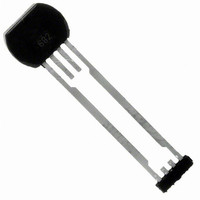
ATS642LSHTN-I1-T Allegro Microsystems Inc, ATS642LSHTN-I1-T Datasheet - Page 8

ATS642LSHTN-I1-T
Manufacturer Part Number
ATS642LSHTN-I1-T
Description
IC SENSOR GEAR TOOTH 4-SIP
Manufacturer
Allegro Microsystems Inc
Type
Special Purposer
Specifications of ATS642LSHTN-I1-T
Output Type
Digital, Open Collector
Sensing Range
120mV Trip, 120mV Release
Voltage - Supply
4 V ~ 24 V
Current - Supply
8mA
Features
Gear Tooth Type
Operating Temperature
-40°C ~ 150°C
Package / Case
4-SIP
Termination Type
Through Hole
Bandwidth
40kHz
Supply Voltage Max
24V
Leaded Process Compatible
Yes
No. Of Pins
4
Mounting Type
Through Hole
Hall Effect Type
Gear Tooth
Supply Voltage Min
4V
Filter Terminals
Through Hole
Rohs Compliant
Yes
Lead Free Status / RoHS Status
Lead free / RoHS Compliant
Current - Output (max)
-
Lead Free Status / RoHS Status
Lead free / RoHS Compliant, Lead free / RoHS Compliant
Available stocks
Company
Part Number
Manufacturer
Quantity
Price
Company:
Part Number:
ATS642LSHTN-I1-T
Manufacturer:
PANASONIC
Quantity:
3 367
Part Number:
ATS642LSHTN-I1-T
Manufacturer:
ALLEGRO/雅丽高
Quantity:
20 000
ATS642LSH
The colored area in the chart above shows the region of allow-
able air gap movement within which the sensor will continue
output switching. The output duty cycle is wholly dependent on
the target’s magnetic signature across the air gap range of move-
ment, and may not always be within specification throughout the
entire operating region (to AG
For more information on these figures and the calculations used to generate them, please refer to the Applications
Note Determining Allowable Air Gap Variation for the ATS642.
(a)
(OPmax)
Peak-Detecting Gear Tooth Sensor with Continuous Calibration
Sensor
Characteristic Allowable Air Gap Movement
).
-0.2
1.2
1.0
0.8
0.6
0.4
0.2
0
0
TEAG
0.2
Allowable Air Gap Movement from TEAG
CAL
0.4
60-0 (60 Tooth Target)
Two-Wire True Zero Speed Miniature Differential
(b)
0.6
ΔTEAG
0.8
Sensor
IN
(mm)
1.0
The axis parameters for the chart are defined in the draw-
ings below. As an example, assume the case where the air gap
is allowed to vary from from the nominal installed air gap
(TEAG
TEAG
TEAG
with an “x” in the chart above.
1.2
TEAG
CAL
OUT
IN
= 0.65 mm (shown in panel c). This case is plotted
1.4
CAL
, panel a) within the range defined by an increase of
OUT
= 0.35 mm (shown in panel b), and a decrease of
1.6
(c)
1.8
115 Northeast Cutoff
1.508.853.5000; www.allegromicro.com
Allegro MicroSystems, Inc.
Worcester, Massachusetts 01615-0036 U.S.A.
Sensor
TEAG
IN
8


