ATS665LSGTN Allegro Microsystems Inc, ATS665LSGTN Datasheet - Page 4
ATS665LSGTN
Manufacturer Part Number
ATS665LSGTN
Description
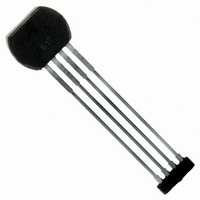
IC SENSOR GEAR TOOTH 4-SIP
Manufacturer
Allegro Microsystems Inc
Type
Special Purposer
Datasheet
1.ATS665LSGTN-T.pdf
(18 pages)
Specifications of ATS665LSGTN
Sensing Range
70% of Air Gap Trip, 30% of Air Gap Release
Voltage - Supply
3.3 V ~ 24 V
Current - Supply
14mA
Current - Output (max)
20mA
Output Type
Digital, Open Collector
Features
Gear Tooth Type
Operating Temperature
-40°C ~ 150°C
Package / Case
4-SIP
Lead Free Status / RoHS Status
Contains lead / RoHS non-compliant
Available stocks
Company
Part Number
Manufacturer
Quantity
Price
Company:

Part Number:
ATS665LSGTN
Manufacturer:
14
Quantity:
4 814


ATS665LSG
OPERATING CHARACTERISTICS
T
Electrical Characteristics
Supply Voltage
Undervoltage Lockout
Reverse Supply Current
Supply Zener Clamp Voltage
Supply Zener Current
Supply Current
Power-On State Characteristics
Power-On State
Power-On Time
Output Stage
Low Output Voltage
Output Current Limit
Output Leakage Current
Output Rise Time
Output Fall Time
Switchpoint Characteristics
Target Speed
Bandwidth
Operate Point
Release Point
Calibration
Initial Calibration
Calibration Update
Operating Characteristics (with 60-0 reference target)
Operational Air Gap
Duty Cycle
Operating Signal
A
= 25°C; unless otherwise noted
Characteristics
True Zero Speed, High Accuracy, Gear Tooth Sensor IC
Symbol
Valid at T
V
CC(UV)
I
f
V
S
V
I
B
B
I
t
AG
RCC
I
OFF
-3dB
V
CC
PO
I
lim
S
t
t
CC
PO
sat
OP
RP
Z
r
f
Z
A
Operating; T
V
I
Test only; V
Output off
Output on
Gear speed < 100 rpm; V
Output = on, I
V
Output = off, V
R
R
Reference target
% of peak-to-peak signal, AG < AG(max)
% of peak-to-peak signal, AG < AG(max)
Start-up, power-on speed ≤ 200 rpm
Running mode operation
Measured from package face to top of target
tooth
AG < AG(max), reference target
Duty cycle spec compliance
CC
= –40°C to 150°C over air gap, typical operating parameters V
CC
OUT
LOAD
LOAD
= I
= –18 V
= 12 V, T
ccon
= 500 Ω, C
= 500 Ω, C
(max) + 3 mA, T
CC
J
SINK
< T
J
OUT
= 28 V, T
Test Conditions
< T
J
LOAD
LOAD
(max)
= 20 mA
= 24 V
J
(max)
= 10 pF
= 10 pF
J
< T
CC
A
= 25°C
J
> V
(max)
CC
(min)
115 Northeast Cutoff
1.508.853.5000; www.allegromicro.com
Allegro MicroSystems, Inc.
Worcester, Massachusetts 01615-0036 U.S.A.
Min.
26.5
3.3
0.5
25
42
60
–
–
–
–
–
–
–
–
–
–
–
0
–
–
–
–
Continuous
High
Typ.
225
1.0
0.6
45
20
70
30
47
–
–
–
–
–
8
8
–
–
–
2
–
–
CC
<V
I
ccon
= 12 V and
12000
Max.
CC
–10
200
400
+ 3
2.5
24
14
14
70
10
52
(max)
–
–
2
2
–
–
–
6
–
(min)
Edges
Unit
rpm
kHz
mm
mV
mA
mA
mA
mA
mA
μA
μs
μs
μs
%
%
%
G
V
V
V
–
3
Related parts for ATS665LSGTN
Image
Part Number
Description
Manufacturer
Datasheet
Request
R

Part Number:
Description:
IC, HALL EFFECT SENSOR, Linear, SOIC-8
Manufacturer:
Allegro Microsystems Inc
Datasheet:
Part Number:
Description:
IC, HALL EFFECT SENSOR, Linear, SOIC-8
Manufacturer:
Allegro Microsystems Inc
Datasheet:
Part Number:
Description:
IC, HALL EFFECT SENSOR, Linear, SOIC-8
Manufacturer:
Allegro Microsystems Inc
Datasheet:

Part Number:
Description:
IC SWITCH INTERFACE 2CHAN 8-SOIC
Manufacturer:
Allegro Microsystems Inc
Datasheet:

Part Number:
Description:
IC SMOKE DETECTOR ION 16-DIP
Manufacturer:
Allegro Microsystems Inc
Datasheet:
Part Number:
Description:
IC SMOKE DETECTOR ION 16-DIP
Manufacturer:
Allegro Microsystems Inc
Datasheet:
Part Number:
Description:
IC SMOKE DETECTOR ION 16-DIP
Manufacturer:
Allegro Microsystems Inc
Datasheet:
Part Number:
Description:
IC SMOKE DETECTOR PHOTO 16-DIP
Manufacturer:
Allegro Microsystems Inc
Datasheet:
Part Number:
Description:
IC SMOKE DETECTOR ION 16-DIP
Manufacturer:
Allegro Microsystems Inc
Datasheet:
Part Number:
Description:
IC SMOKE DETECTOR PHOTO 16-DIP
Manufacturer:
Allegro Microsystems Inc
Datasheet:
Part Number:
Description:
IC SMOKE DETECTOR PHOTO 16-DIP
Manufacturer:
Allegro Microsystems Inc
Datasheet:
Part Number:
Description:
IC SMOKE DETECTOR ION 16-DIP
Manufacturer:
Allegro Microsystems Inc
Datasheet:
Part Number:
Description:
IC SMOKE DETECTOR PHOTO 16-SOIC
Manufacturer:
Allegro Microsystems Inc
Datasheet:

Part Number:
Description:
IC LED DRIVER HIGH BRIGHT 16-QFN
Manufacturer:
Allegro Microsystems Inc
Datasheet:

Part Number:
Description:
IC LED DRIVER AUTOMOTIVE 8-SOIC
Manufacturer:
Allegro Microsystems Inc
Datasheet: