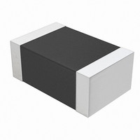
NTCS0805E3153JMT Vishay, NTCS0805E3153JMT Datasheet - Page 7

NTCS0805E3153JMT
Manufacturer Part Number
NTCS0805E3153JMT
Description
THERMISTOR NTC 15K OHM 0805 SMD
Manufacturer
Vishay
Series
2381r
Type
NTCr
Specifications of NTCS0805E3153JMT
Resistance In Ohms @ 25°c
15K
Resistance Tolerance
±5%
B Value Tolerance
±1%
B25/85
3700K
Operating Temperature
-40°C ~ 150°C
Power - Max
210mW
Mounting Type
Surface Mount
Package / Case
0805 (2012 Metric)
Description Of Terminals
Leadless
Mounting Style
Surface Mount
Pin Count
2
Screening Level
Automotive
Sensitivity Index
3700K
Resistance @ 25c
15kohm
Thermal Time Constant
10s
Percentage Of Resistance Tolerance @ 25c
±5
Accuracy
±1
Operating Temperature Min Deg. C
-40C
Operating Temperature Max Deg. C
150C
Product Length (mm)
2mm
Product Height (mm)
0.8mm
Product Depth (mm)
1.25mm
Thermistor Type
NTC
Resistance
15kohm
Thermistor Tolerance
± 5%
Beta Value (k)
3700K
Operating Temperature Range
-40°C To +150°C
Thermistor Case Style
0603
No. Of Pins
2
Beta Upper Temperature
85°C
Rohs Compliant
Yes
Beta Lower Temperature
25°C
Lead Free Status / RoHS Status
Lead free / RoHS Compliant
B0/50
-
B25/50
-
B25/75
-
B25/100
-
Lead Length
-
Lead Free Status / Rohs Status
Lead free / RoHS Compliant
Other names
2381 615 53153
238161553153
BC2293TR
238161553153
BC2293TR
Available stocks
Company
Part Number
Manufacturer
Quantity
Price
Part Number:
NTCS0805E3153JMT
Manufacturer:
VISHAY/威世
Quantity:
20 000
NTCS0805E3.....T
Vishay BCcomponents
SOLDERING CONDITIONS
This SMD thermistor is only suitable for wave or reflow soldering, in accordance with JEDEC J-STD-020. The maximum
temperature of 260 °C during 40 s should not be exceeded.
Typical examples of a soldering processes that will provide reliable joints without damage, are shown below.
TESTS AND REQUIREMENTS
PACKAGING
TAPE SPECIFICATIONS
All tape specifications are in accordance with IEC 60286-3. Basic dimensions are given below. Carrier tape material is paper.
PAPER TAPE
www.vishay.com
22
THE PRODUCT DESCRIBED HEREIN AND THIS DATASHEET ARE SUBJECT TO SPECIFIC DISCLAIMERS, SET FORTH AT
SOLDERABILITY AND RESISTANCE TO SOLDERING HEAT
IEC 60068-2-58
300
250
200
150
100
50
0
6
D
0
0
≈ 245 °C
260 °C
215 °C
180 °C
130 °C
A
0
B
50
P
0
1
P
Reflow Soldering
TEST METHOD
2
2 K/s
P
0
100
T
C
Time (s)
150
For technical questions, contact:
10 s
10 s
F
E
JWB288
This datasheet is subject to change without notice.
40 s
1.3
1
Resistance to soldering heat
SMD 0805, Glass Protected
W
200
Solderability
Dimensions of the solder lands
NTC Thermistors
1.0
TEST
250
T
T
1
3.0
Notes
• Measured 0.3 mm above base pocket
• P
DIMENSIONS OF PAPER TAPE in millimeters
PARAMETER
A
B
W
E
F
D
P
P
P
T tape thickness
T
1
1
0
0
0
0
0
1
2
cover tape
pitch cumulative error over any 10 pitches ± 1.0 mm
nlr@vishay.com
(1)
(1)
(2)
300
250
200
150
100
50
0
0
PROCEDURE
10 s at 260 °C
Lead (Pb)-free Reflow Soldering Profile
2 s at 235 °C
≈ 245 °C
≈ 170 °C
260 °C
235 °C
50
100
2 K/s
max.
≈ 120 °C
DIMENSION
150
Time (s)
< 0.1
2.35
1.75
1.55
Min. 95 % of surface wetted
1.7
8.0
3.5
4.0
4.0
2.0
1.1
200
www.vishay.com/doc?91000
REQUIREMENTS
Document Number: 29044
R/R < 5 %
250
20 s min.
40 s max.
Revision: 09-Mar-11
≈ 60 s
TOLERANCE
6 K/s
max.
limit
normal
300
± 0.05
± 0.05
± 0.05
± 0.2
± 0.1
± 0.2
± 0.1
± 0.1
± 0.1
Max.
-
350


