P100B TPI (Test Products Int), P100B Datasheet - Page 2
P100B
Manufacturer Part Number
P100B
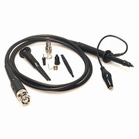
Description
PROBE OSC 100MHZ X10 1.2M CABLE
Manufacturer
TPI (Test Products Int)
Type
Passiver
Datasheet
1.1P20B.pdf
(2 pages)
Specifications of P100B
Attenuation Value
10:1
Bandwidth
100MHz
Resistance - Input
10M
Voltage - Max
CAT II 300V, CAT I 600V
Capacitance - Input
16pF
Cable Length
47.244" (1200.00mm)
Color
-
Other names
290-1001


The
Value
Leader
™
Model Bandwidth Attenuation Cable Input Impedance
IP060
IP250
SP 60B
SP 100B
SP150B
SP 200B
SP 250B
SP 300B
1P20B
P100B
P100BR
P200B
P250
P250R
P250B
P250BR
P1,000B
FAQ
Can TPI oscilloscope probes be used with Tektronix and Hewlett
Packard scopes?
Yes, TPI oscilloscope probes can be used with most major brands
of scopes.
Why is selecting a probe with the correct bandwidth important?
Choosing a probe with the correct bandwidth enables you to use
your scope to its full potential.
Why do TPI oscilloscope probes have a compensation range
and compensation adjustment?
Since the input of every oscilloscope is different our probes have
a compensation adjustment so the capacitance of the probe can
be adjusted to match the capacitance of the scope input. The
compensation range is the range of adjustment available.
Matching probe and scope capacitance is important to prevent
waveform distortion.
Oscilloscope Probe Specifications
250MHz
100MHz
150MHz
200MHz
250MHz
300MHz
100MHz
100MHz
200MHz
250MHz
250MHz
250MHz
250MHz
60MHz
60MHz
15MHz
1GHz
OSCILLOSCOPE PROBES
x100
x100
x10
x10
x10
x10
x10
x10
x10
x10
x10
x10
x10
x10
x10
x10
x1
x1
x1
x1
x1
x1
x1
x1
x1
Length
1.5M
1.5M
1.2M
1.2M
1.2M
1.2M
1.2M
1.2M
1.2M
1.2M
1.2M
1.2M
1.2M 100Meg
1.2M 100Meg
1.2M
1.2M
1.0M
1Meg
10Meg
1Meg
10Meg
10Meg
10Meg
10Meg
10Meg
10Meg
10Meg
10Meg
10Meg
10Meg
10Meg
10Meg
1Meg
1Meg
1Meg
1Meg
1Meg
1Meg
1Meg
5003pF
R
SPECIFICATIONS
SP SERIES, SWITCHABLE
IP SERIES, SWITCHABLE
200pF
200pF
47pF
47pF
47pF
47pF
47pF
47pF
47pF
18pF
16pF
15pF
15pF
14pF
13pF
16pF
16pF
15pF
14pF
14pF
22pF
22pF
NON-SWITCHABLE
6.5pF
6.5pF
L
DC + peak AC
Max Input V
1,200V
1,200V
What is the benefit of a probe with X1 and X10 switchable
attenuation?
Passive X10 probes allow you to read a signal 10 times the
amplitude of that viewed with a X1 probe. Example: an eight-division
graticule on 5V/Div setting would display a 40 volt peak-to-peak signal
using the X1 setting. You can view a 400 volt signal using the X10
setting.
What is readout?
Readout is an activator pin that protrudes out of the BNC connector of
an X10 or X100 probe that completes a circuit. There are contacts
around the BNC connector on the front of the oscilloscope and the
attenuation is automatically set. If your scope does
not have contacts around the BNC connector, it does not need this
feature.
What probe should I buy?
Select a probe that is at least the same bandwidth as the oscilloscope
you intend to use; however, for optimum performance, select a probe
with two times the bandwidth of your test instrument.
600V
600V
600V
600V
600V
600V
600V
600V
600V
600V
600V
600V
600V
600V
600V
1.5ns
5.8ns
3.5ns
2.3ns
1.8ns
1.4ns
1.1ns
3.5ns
3.5ns
1.8ns
1.4ns
1.4ns
1.4ns
1.4ns
Rise
Time
23ns
6ns
NA
Compensation
20 ~ 45 pF
10 ~ 60pF
10 ~ 30pF
10 ~ 35pF
10 ~ 35pF
10 ~ 35pF
10 ~ 35pF
10 ~ 35pF
10 ~ 35pF
10 ~ 35pF
10 ~ 35pF
10 ~ 35pF
10 ~ 35pF
10 ~ 35pF
10 ~ 35pF
Range
NA
Readout
Yes
Yes
Yes
Yes
NA
NA
NA
NA
NA
NA
NA
NA
NA
NA
NA
NA
NA
IEC1010
CAT II
CAT II
CAT II
CAT II
CAT II
CAT II
CAT II
CAT II
CAT II
CAT II
CAT II
CAT II
CAT II
CAT II
FAQ
What can you measure with a differential probe?
With 20 MHz bandwidth, a switchable attenuation of 20:1,
and 200:1 (part no. ADF25), you can measure high-voltage
circuits, motor speed controls, power supply design, and
high-power electronic converters.
What comes in the probe set?
You will receive one differential probe, 2 probe tips, and 2
retractable sprung probes for accessing small wires for
measurements.
Why is common rejection ratio (CMMR) important for
differential probes?
CMMR is a measure of how well a differential probe will
reject signals common to both test points, leaving the
desired signal to be displayed by the scope
FUNCTION
Bandwidth
Accuracy
Risetime
CMRR (Typical)
50Hz
20kHz
200kHz
Input Impedance
Input Voltage
Maximum Differential
Output Voltage
Offset (typical)
Common Mode
Noise (typical)
Output Source
Impedance
Operating Temperature
Power Requirements
Power Supply
Input Leads
IEC1010
Differential Probe Specifications
DIFFERENTIAL PROBES
1 @ 1kHz. 8 @1 MHz
± 7V minimum 2K load
± 1,400V DC Inc. Pk AC
±140V DC Inc.Pk AC@
± 1,400VDC Inc. Pk AC
45 cm double insulated
200:1 or 1,000V RMS
DC -25 MHz (-3dB)
44 mm safety plugs
20:1 or 100V RMS
PVC terminated in
between inputs
or 1,000V RMS
side to ground
4M/10pf each
0.7mV RMS
ADF25
8M/5pF
CAT III
-80dB
-60dB
-50dB
± 2%
14nS
SPECIFICATIONS
4 AA cell or 6V main adapters: DC/600mA or DC/800mA
-10° C to + 40° C (14°F to 104°F)
<± 5mV -10° C to + 40° C
1 @ 1kHz. 8 @1 MHz
± 7V minimum 2K load
± 1,400V DC Inc. Pk AC
45 cm double insulated
±170V DC Inc.Pk AC@
± 1,400VDC Inc. Pk AC
100:1 or 500V RMS
DC -25 MHz (-3dB)
44 mm safety plugs
10:1 or 50V RMS
PVC terminated in
between inputs
or 1,000V RMS
side to ground
What does the maximum differential voltage specification
tell me?
This specification provides you with the maximum voltage
between the inputs the differential probe can be subjected to.
This is important because the maximum voltage should never
be exceeded.
What is input impedance?
Impedance is a measure of how much a signal will be
restricted. In general, it is best to have high resistance and low
capacitance to ensure signal quality, accuracy of tests, and to
ensure the probe doesn’t load down the circuit under test.
4M/10pf each
0.7mV RMS
Not included
ADF25A
8M/5pF
± 2%
-86dB
-66dB
-56dB
CATIII
14nS
± 7V minimum 50K load
1,000:1 or 5,000V RMS
± 7,000V DC Inc. Pk AC
60 cm double insulated
±700V DC Inc.Pk AC@
± 7,000VDC Inc. Pk AC
100:1 or 400V RMS
DC -70 MHz (-3dB)
Rubber terminated
or 2,500V RMS
in sprung hooks
10M/10pf each
between inputs
side to ground
0.9mV RMS
ADF25C
20M/5pF
-80dB
-60dB
-50dB
± 2%
14nS
CATII
50