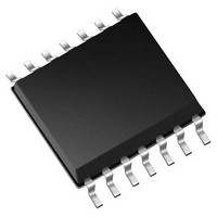
MCP4431-103E/ST Microchip Technology, MCP4431-103E/ST Datasheet - Page 18

MCP4431-103E/ST
Manufacturer Part Number
MCP4431-103E/ST
Description
IC POT 10K QUAD 7BIT 20TSSOP
Manufacturer
Microchip Technology
Specifications of MCP4431-103E/ST
Package / Case
20-TSSOP (0.173", 4.40mm Width)
Resistance (ohms)
10K
Taps
129
Number Of Circuits
4
Temperature Coefficient
*
Memory Type
Volatile
Interface
I²C, 2-Wire Serial
Voltage - Supply
1.8 V ~ 5.5 V
Operating Temperature
-40°C ~ 125°C
Mounting Type
Surface Mount
Number Of Pots
Quad
Taps Per Pot
129
Resistance
10 KOhms
Wiper Memory
Volatile
Digital Interface
I2C
Operating Supply Voltage
1.8 V to 5.5 V
Supply Current
600 uA
Maximum Operating Temperature
+ 125 C
Minimum Operating Temperature
- 40 C
Mounting Style
SMD/SMT
Supply Voltage (max)
5.5 V
Supply Voltage (min)
1.8 V
Lead Free Status / RoHS Status
Lead free / RoHS Compliant
Available stocks
Company
Part Number
Manufacturer
Quantity
Price
Part Number:
MCP4431-103E/ST
Manufacturer:
MICROCHIP/微芯
Quantity:
20 000
dB Calculations (Voltage)
Digital Potentiometer Solutions
Logarithmic Steps
Logarithmic steps are desirable since the human ear hears
in a logarithmic manner. The use of a linear potentiometer
can approximate a log potentiometer, but with fewer steps.
An 8-bit potentiometer can achieve fourteen 3 dB log steps
plus a 100% (0 dB) and a mute setting.
The figure below shows a block diagram of one of the
MCP44X1 resistor networks being used to attenuate an
input signal. In this case, the attenuation will be ground
referenced. Terminal B can be connected to a common mode
voltage, but the voltages on the A, B and Wiper terminals
must not exceed the MCP44X1 device’s V
limits.
Signal Attenuation Block Diagram - Ground Referenced
The following equation shows how to calculate voltage dB
gain ratios for the digital potentiometer.
More detail on this can be found in Section 8.5 of the
MCP444X/446X Data Sheet (DS22265).
18
Digital Potentiometer Design Guide
DD
/V
SS
voltage
Wheatstone Bridge Trimming
The following circuit shows a Wheatstone Bridge with current
limiting. In a Wheatstone Bridge, there are four resistive
elements. In this example, two are fixed value (R1 and R2),
there is a resistive sensor (R
digital potentiometer in rheostat configuration to calibrate the
circuit due to variations of the resistive sensor. This sensor
could be for temperature or weight measurement.
At a default condition the sensor should be a given value, but
this value will change from device to device. To compensate
for the resistive changes in the R1 plus R
bridge, the Rheo2 would be modified for the R2 plus Rheo2
leg of the bridge. This would be done so that the voltages of
V
is V
Now as the conditions on the sensor change, the resistance
of the sensor will change, causing the V
change. The delta voltage between V
be used to determine the state of the system (temperature,
weight, etc.).
Rheo 1 is used in a rheostat mode to limit the current or trim
the current through the Wheatstone Bridge.
Implementing a More Precise Rheostat
The R
much as ±20%, so a device with a 10 kΩ R
have an R
a system, this variation for the rheostat value may not be
desirable. This variation can be calibrated out to make a
precise rheostat, at a cost of the resolution of the device.
If we design the application circuit where this rheostat
only operates from 0Ω to 8 kΩ, all digital potentiometer
devices (over process) will meet this requirement. Now with
calibration, we will need to ensure that the wiper value is
limited to a value where the rheostat value is the closest
resistance value to the desired rheostat target value of 8
kΩ. The worst case (lowest) wiper value occurs when the R
value is 12 kΩ. In this case, a wiper value of 171. results
in a resistance of 8016Ω. This results in a resolution of
approximately 7.4 bits, or 0.58%.
In potentiometer mode, the process variation of the R
may not be an application issue since the device is operating
as a voltage divider.
BRG
BRG
1
AB
and V
1
value of a typical digital potentiometer can vary as
= V
AB
BRG
BRG
value as small as 8 kΩ, as large as 12 kΩ. In
2
2
.
are at their desired levels. Many times this
SENSOR
) and then there is the
BRG
BRG
1
SENSOR
and V
2
AB
voltage to
value could
BRG
leg of the
2
can then
AB
value
AB


