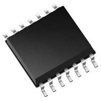
MCP4451-103E/ST Microchip Technology, MCP4451-103E/ST Datasheet - Page 17

MCP4451-103E/ST
Manufacturer Part Number
MCP4451-103E/ST
Description
IC POT 10K QUAD 8BIT 20TSSOP
Manufacturer
Microchip Technology
Specifications of MCP4451-103E/ST
Package / Case
20-TSSOP (0.173", 4.40mm Width)
Resistance (ohms)
10K
Taps
257
Number Of Circuits
4
Temperature Coefficient
*
Memory Type
Volatile
Interface
I²C, 2-Wire Serial
Voltage - Supply
1.8 V ~ 5.5 V
Operating Temperature
-40°C ~ 125°C
Mounting Type
Surface Mount
Number Of Pots
Quad
Taps Per Pot
257
Resistance
10 KOhms
Wiper Memory
Volatile
Digital Interface
I2C
Operating Supply Voltage
1.8 V to 5.5 V
Supply Current
600 uA
Maximum Operating Temperature
+ 125 C
Minimum Operating Temperature
- 40 C
Mounting Style
SMD/SMT
Supply Voltage (max)
5.5 V
Supply Voltage (min)
1.8 V
Lead Free Status / RoHS Status
Lead free / RoHS Compliant
Available stocks
Company
Part Number
Manufacturer
Quantity
Price
Company:
Part Number:
MCP4451-103E/ST
Manufacturer:
ALTERA
Quantity:
339
Digital Potentiometer Solutions
Application Circuits and Techniques
Digital potentiometers are a good fit for applications to trim
offset and gain in amplifier circuits. In this following circuit,
a resistor ladder is used to create a voltage window where
Pot1 is used to trim the desired offset for the inverting
amplifier. A second potentiometer (Pot2) is used in a
rheostat mode along with resistor R3 to control the gain of
the amplifier. The step resistance of Pot2 relative to resistor
R3 determines if the gain trimming is a fine adjustment or a
course adjustment. Capacitor C1 is for compensation of the
op amp and to inhibit the output from oscillating.
In this circuit, there is no interaction between the offset
trimming and the gain trimming, but the input signal (V
loaded by the resistance of R3 plus Pot2’s R
Inverting Amplifier with Offset and Gain Trimming
In the following circuit, a resistor ladder is used to create
a voltage window where Pot1 is used to trim the desired
offset for the non-inverting amplifier. A second potentiometer
is used in a rheostat mode to control the gain of the
amplifier. The step resistance of Pot2 relative to resistor R3
determines if the gain trimming is a fine adjustment or a
course adjustment. Capacitor C1 is for compensation of the
op amp and to inhibit the output from oscillating.
In this circuit, there is an interaction between the offset
trimming and the gain trimming. To minimize this interaction,
Pot2 should be small compared to resistor R3 and Pot1
should be small relative to the sum of R1 and R2. But the
input signal (V
Non-Inverting Amplifier with Offset and Gain Trimming
Additional information can be found in application note AN1316.
IN
) is not loaded.
BW
value.
IN
) is
In the following circuit, a resistor ladder is used to create a
voltage window where Pot1 is used to trim the desired offset
for the band pass filter. This resistor ladder setting also
works with capacitor C2 to set the high pass filter frequency.
A second potentiometer (Pot2) is used in a rheostat mode
along with R3 and R4 to control the gain of the amplifier.
The step resistance of Pot2 relative to resistors R3 and R4
determines if the gain trimming is a fine adjustment or a
course adjustment. Capacitor C1 along with Pot2, R3 and R4
is used to set the low pass filter.
Capacitor C1 is also used for compensation of the Op Amp
and to inhibit the output from oscillating.
If capacitor C1 is not present, then the circuit is a high pass
filter, while if capacitor C2 is not present then the circuit is a
low pass filter.
Band Pass Filter with Offset and Gain Trimming
The following circuit will the use of an RC filter (Potx and
Cx) will filter at the selected frequency. that frequency is
determined by the rheostat value (R
capacitor value (Cx). each additional stage of the RC filter is
used to enhance the roll-off characteristics for the filter. The
capacitors Cx should be the same, while the wiper values
of the Pots should be similar. The differences would be to
compensate for the slight variations of the R
each Pot and the variations of the capacitors.
Programmable Filter
Digital Potentiometer Design Guide
BW
) of the Pot and the
AB
values of
17


