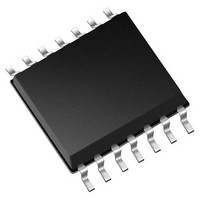
MCP4451-503E/ST Microchip Technology, MCP4451-503E/ST Datasheet - Page 43

MCP4451-503E/ST
Manufacturer Part Number
MCP4451-503E/ST
Description
IC POT 50K QUAD 8BIT 20TSSOP
Manufacturer
Microchip Technology
Specifications of MCP4451-503E/ST
Package / Case
20-TSSOP (0.173", 4.40mm Width)
Resistance (ohms)
50K
Taps
257
Number Of Circuits
4
Temperature Coefficient
*
Memory Type
Volatile
Interface
I²C, 2-Wire Serial
Voltage - Supply
1.8 V ~ 5.5 V
Operating Temperature
-40°C ~ 125°C
Mounting Type
Surface Mount
Number Of Pots
Quad
Taps Per Pot
257
Resistance
50 KOhms
Wiper Memory
Volatile
Digital Interface
I2C
Operating Supply Voltage
1.8 V to 5.5 V
Supply Current
600 uA
Maximum Operating Temperature
+ 125 C
Minimum Operating Temperature
- 40 C
Mounting Style
SMD/SMT
Supply Voltage (max)
5.5 V
Supply Voltage (min)
1.8 V
Lead Free Status / RoHS Status
Lead free / RoHS Compliant
Available stocks
Company
Part Number
Manufacturer
Quantity
Price
Part Number:
MCP4451-503E/ST
Manufacturer:
MICROCHIP/微芯
Quantity:
20 000
4.2.1.1
There are two Terminal Control (TCON) Registers.
These are called TCON0 and TCON1. Each register
contains 8 control bits, four bits for each Wiper.
Register 4-1
while
register.
The state of each resistor network terminal connection
is individually controlled. That is, each terminal
connection (A, B and W) can be individually connected/
disconnected from the resistor network. This allows the
system to minimize the currents through the digital
potentiometer.
REGISTER 4-1:
2010 Microchip Technology Inc.
bit 8
Legend:
R = Readable bit
-n = Value at POR
bit 8
bit 7
bit 6
bit 5
bit 4
bit 3
bit 2
bit 1
bit 0
Note 1:
R-1
D8
Register 4-2
These bits do not affect the wiper register values.
describes each bit of the TCON0 register,
Terminal Control (TCON) Registers
D8: Reserved. Forced to ‘1’
R1HW: Resistor 1 Hardware Configuration Control bit
This bit forces Resistor 1 into the “shutdown” configuration of the Hardware pin
1 = Resistor 1 is NOT forced to the hardware pin “shutdown” configuration
0 = Resistor 1 is forced to the hardware pin “shutdown” configuration
R1A: Resistor 1 Terminal A (P1A pin) Connect Control bit
This bit connects/disconnects the Resistor 1 Terminal A to the Resistor 1 Network
1 = P1A pin is connected to the Resistor 1 Network
0 = P1A pin is disconnected from the Resistor 1 Network
R1W: Resistor 1 Wiper (P1W pin) Connect Control bit
This bit connects/disconnects the Resistor 1 Wiper to the Resistor 1 Network
1 = P1W pin is connected to the Resistor 1 Network
0 = P1W pin is disconnected from the Resistor 1 Network
R1B: Resistor 1 Terminal B (P1B pin) Connect Control bit
This bit connects/disconnects the Resistor 1 Terminal B to the Resistor 1 Network
1 = P1B pin is connected to the Resistor 1 Network
0 = P1B pin is disconnected from the Resistor 1 Network
R0HW: Resistor 0 Hardware Configuration Control bit
This bit forces Resistor 0 into the “shutdown” configuration of the Hardware pin
1 = Resistor 0 is NOT forced to the hardware pin “shutdown” configuration
0 = Resistor 0 is forced to the hardware pin “shutdown” configuration
R0A: Resistor 0 Terminal A (P0A pin) Connect Control bit
This bit connects/disconnects the Resistor 0 Terminal A to the Resistor 0 Network
1 = P0A pin is connected to the Resistor 0 Network
0 = P0A pin is disconnected from the Resistor 0 Network
R0W: Resistor 0 Wiper (P0W pin) Connect Control bit
This bit connects/disconnects the Resistor 0 Wiper to the Resistor 0 Network
1 = P0W pin is connected to the Resistor 0 Network
0 = P0W pin is disconnected from the Resistor 0 Network
R0B: Resistor 0 Terminal B (P0B pin) Connect Control bit
This bit connects/disconnects the Resistor 0 Terminal B to the Resistor 0 Network
1 = P0B pin is connected to the Resistor 0 Network
0 = P0B pin is disconnected from the Resistor 0 Network
R/W-1
R1HW
describes each bit of the TCON1
TCON0 BITS
W = Writable bit
‘1’ = Bit is set
R/W-1
R1A
(1)
R/W-1
R1W
U = Unimplemented bit, read as ‘0’
‘0’ = Bit is cleared
R/W-1
R1B
The value that is written to the specified TCON register
will appear on the appropriate resistor network
terminals when the serial command has completed.
On a POR/BOR these registers are loaded with
1FFh (9-bit), for all terminals connected. The Host
Controller needs to detect the POR/BOR event and
then update the Volatile TCON register values.
R0HW
R/W-1
x = Bit is unknown
R/W-1
R0A
MCP443X/5X
R/W-1
R0W
DS22267A-page 43
R/W-1
R0B
bit 0


