84-5031.2B20 EAO, 84-5031.2B20 Datasheet - Page 10
84-5031.2B20
Manufacturer Part Number
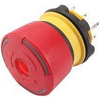
84-5031.2B20
Description
SWITCH, EMERGENCY STOP, 1NO/1NC, 250VAC
Manufacturer
EAO
Datasheet
1.84-7111.600.pdf
(13 pages)
Specifications of 84-5031.2B20
Contact Configuration
DPST-1NO / 1NC
Switch Operation
Twist Release
Contact Voltage Ac Nom
250V
Contact Current Max
3A
Illumination Color
Red
Actuator Style
Mushroom
Lead Free Status / RoHS Status
Lead free / RoHS Compliant


Technical Data
Climate resistance
Damp heat, cyclic
96 hours, +25 °C / 97%, +55 °C / 93% relative humidity, as per
EN IEC 60068-2-30
Damp heat, steady
56 days, +40 °C / 93% relative humidity, as per EN IEC 60068-2-78
Dry heat
96 hours, +70 °C, as per EN IEC 60068-2-2
Low temperature
96 hours, −40 °C, as per EN IEC 60068-2-1
Saline mist
96 Stunden, +35 °C in chemical solution NaCl, as per
EN IEC 60068-2-11
Approvals
Approbations
SEV
UL
Declaration of conformity
CE
Switching element illuminated pushbutton
Switching system
Short-travel switching system with 2 independent contact points and
tactile operation. Guarantees reliable switching even of very light loads.
Fitted with 1 normally open contact.
Material
Connection cable
Polyvinylchloride (PVC), short-time heat-resistant up to 105 °C
Material of contact
Silver alloy gold plated
Switching element
Thermoplastic polyester (PET, PBT), as per UL 94 V0 and
Polyacetale (POM), as per UL 94 HB
Mechanical characteristics
Terminals
Plug-in terminals 2.8 x 0.8 mm (solderable)
Flat ribbon cable 0.5 mm²
PCB terminal
Actuating force
4.0 N ±0.2 N (measured at the lens)
Actuating travel
~0.5 mm
Rebound time
≤1 ms
Resistance to heat of soldering
260 °C, 5 s (PCB assembly)
350 °C, 10 s (when using a soldering iron)
as per EN IEC 60068-2-20
Mechanical lifetime
≥1 million cycles of operations
127
Electrical characteristics
Illumination
Single-Chip or Multi-Chip LED, green, orange, red, yellow, white and
blue
Operation Voltage
Current consumption
Contact resistance
Starting value (initial) ≤100 mΩ, as per DIN IEC 60512-2
Isolation resistance
≥1 G Ω between all terminals at 100 VDC, as per DIN IEC 60512-2
Electrical life
as per EN IEC 60512-5
5 million
5 million
2 million
2 million
300 000
250 000
1 million
1 million
1 million
5 million
1.5 million
100 000
500 000
300 000
100 000
Switch rating
Voltage
Current
Power
Electric strength
500 VAC, 50 Hz, 1 min. as per DIN IEC 60512-2
Environmental conditions
Storage temperature
−40 °C ... +85 °C
Operating temperature
−25 °C ... +70 °C
Protection degree
For IP67 back protection, cable version only, use blind plug Typ-Nr.
84-900
Shock resistance
(semi-sinusoidal)
max. 100 m/s², pulse width 11 ms, 3-axis, as per EN IEC 60068-2-27
Vibration resistance
(sinusoidal)
max. 50 m/s² at 10 Hz ... 500 Hz, 10 cycles, 3-axis, as per
EN IEC 60068-2-6
cycles of operation
cycles of operation
cycles of operation
cycles of operation
cycles of operation
cycles of operation
cycles of operation
cycles of operation
cycles of operation
cycles of operation
cycles of operation
cycles of operation
cycles of operation
cycles of operation
cycles of operation
50 mVAC/DC ... 42 VAC/DC
10 uA ... 100 mA
max. 2 W
12 VDC
40 mA
24 VAC, 50 mA at 480 Ω
24 VAC, 100 mA at 240 Ω
42 VAC, 50 mA at 840 Ω
42 VAC, 100 mA at 420 Ω
42 VAC, 100 mA at cosφ 0.4
42 VAC, 200 mA at cosφ 0.395
12 VDC, 250 mA at 48 Ω
24 VDC, 50 mA at 480 Ω
24 VDC, 100 mA at 240 Ω
42 VDC, 25 mA at 1680 Ω
42 VDC, 50 mA at 840 Ω
42 VDC, 100 mA at 420 Ω
24 VDC, 200 mA at L/R=30 ms
42 VDC, 100 mA at L/R=30 ms
42 VDC, 200 mA at L/R=30 ms
24 VDC
20 mA
Series 84
Related parts for 84-5031.2B20
Image
Part Number
Description
Manufacturer
Datasheet
Request
R

Part Number:
Description:
Switch, E-STOP, Illuminated, 1 NO/1 NC, PLUG IN TerminalS
Manufacturer:
EAO Switch
Datasheet:
Part Number:
Description:
Manufacturer:
Huber + Suhner AG
Datasheet:

Part Number:
Description:
84 MODII HORZ DR CE 100CL/115
Manufacturer:
TE Connectivity
Datasheet:

Part Number:
Description:
SCRs 8.0 Amp 400 Volt
Manufacturer:
STMicroelectronics
Datasheet:

Part Number:
Description:
SCRs 8.0 Amp 800 Volt
Manufacturer:
STMicroelectronics
Datasheet:

Part Number:
Description:
Power Inductors 1.5H 10mA W/Leads
Manufacturer:
Triad Magnetics
Datasheet:
Part Number:
Description:
Power Inductors 0.5H 300Ma w/leads
Manufacturer:
Triad Magnetics
Datasheet:

Part Number:
Description:
INDICATOR, ALUMINUM
Manufacturer:
EAO
Datasheet:

Part Number:
Description:
SINGLE CHIP LED/ T1 BI-PIN/ 2.1VDC/20MA - RED
Manufacturer:
EAO
Datasheet:

Part Number:
Description:
INDICATOR, INCAND LAMP, BI PIN
Manufacturer:
EAO
Datasheet:
Part Number:
Description:
INDICATOR, BI-PIN
Manufacturer:
EAO
Datasheet:

Part Number:
Description:
INDICATOR, INCAND LAMP, MIDGET GROOVED
Manufacturer:
EAO
Datasheet: