FB1W-HW4B-Y202-R IDEC, FB1W-HW4B-Y202-R Datasheet - Page 54
FB1W-HW4B-Y202-R
Manufacturer Part Number
FB1W-HW4B-Y202-R
Description
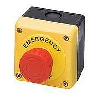
SWITCH, EMERGENCY STOP, 2NC, 600VAC
Manufacturer
IDEC
Datasheet
1.HW1A-B1-R.pdf
(61 pages)
Specifications of FB1W-HW4B-Y202-R
Contact Configuration
DPST-NC
Switch Operation
Pushlock Turn Reset
Contact Voltage Ac Nom
600V
Contact Voltage Dc Nom
220V
Contact Current Max
10A
Actuator Style
Mushroom
Switch Terminals
Screw
Rohs Compliant
Yes
Lead Free Status / RoHS Status
Lead free / RoHS Compliant


Oiltight Switches & Pilot Devices
ø40mm Head Push-Pull (HW1B-Y2)
Illuminated E-Stop Pushbuttons (HW1E-LV4)
Terminal Arrangement (Bottom View)
HW1E-BV4
Emergency Stop Stations
M3.5 Terminal Screw
Terminal Cover
Box Cover Mouting Screws
13
76
.2 (NC)
.1 (NC)
25.5
(1NO-1NC)
Side
.3 (NO)
.4 (NO)
TOP Marking
M3.5 Terminal Screw
Lamp Terminal
Panel Thickness 0.8 to 6
HW1B-V4R
Locking Ring
63
61
HW1E-LV4
Gasket
A
Box Cover
29.4
11.5
LAMP
USA: 800-262-IDEC
59.5
14
32
.2 (NC)
.1 (NC)
Box Base
(1NO-1NC)
TOP
X1
X2
.3 (NO)
.4 (NO)
ø40mm Head Unibody Pushlock Turn Reset (HW1B-BV4)
M3.5 Terminal Screw
Operator
Pushlock Turn Reset
Pushlock Key Reset
Push Pull
Terminal Cover
Canada: 888-317-IDEC
Panel Thickness 0.8 to 6
Dimension A (mm)
32
32 (Key inserted: 49.4)
25.5
Mounting Hole
Unit
HW1B-V3
HW1B-V4
HW1B-X4
HW1B-Y2
HW1B-V5
TOP Marking
Locking Ring
R0.8 max.
Gasket
46
48
Vertical Spacing
50 mm
60 mm
ø22mm - HW Series
3.2
11.5
+0.2
0
14
Mounting Hole Layout
The minimum mounting centers shown be-
low are applicable to E-Stop switches with
one layer of contact blocks (two contact
blocks). When two layers of contact blocks
are mounted, determine the minimum
mounting centers for ease of wiring.
4-M4 Tapped Holes for Rear Mounting
(Depth: 10 mm)
32
2-Front Mounting Holes
Horizontal Spacing
50 mm
60 mm
62
15.5
ø14 Knockout
Dimensions (mm)
553
Related parts for FB1W-HW4B-Y202-R
Image
Part Number
Description
Manufacturer
Datasheet
Request
R

Part Number:
Description:
SWITCH, EMERGENCY STOP, 1NO/1NC, 600VAC
Manufacturer:
IDEC
Datasheet:

Part Number:
Description:
E-Stop Station
Manufacturer:
IDEC
Datasheet:
Part Number:
Description:
SWITCH; WITH ENCLOSURE; 40MM PUSHLOCK; TURN RESET; METAL; 1 NC/ 1NO
Manufacturer:
IDEC Corporation
Datasheet:
Part Number:
Description:
SWITCH; WITH ENCLOSURE; 40MM PUSH PULL RESET; METAL; 1 NC/ 1NO
Manufacturer:
IDEC Corporation
Datasheet:
Part Number:
Description:
SWITCH; WITH ENCLOSURE; 40MM PUSH PULL RESET; METAL; 2 NC
Manufacturer:
IDEC Corporation
Datasheet:
Part Number:
Description:
SWITCH; WITH ENCLOSURE; 29MM PUSHLOCK; TURN RESET; METAL; 2 NC
Manufacturer:
IDEC Corporation
Datasheet:
Part Number:
Description:
SWITCH; WITH ENCLOSURE; 40MM; EMO PUSHLOCK; TURN RESET; METAL; 2 NC
Manufacturer:
IDEC Corporation
Datasheet:
Part Number:
Description:
Cable; Between IDEC MicroSmart (port 1 or 2) and HG2F/3F/4F; 5 ft.
Manufacturer:
IDEC Corporation
Datasheet:
Part Number:
Description:
Cable; Between IDEC Micro^3C/ONC/MicroSmart (port 2) PLCs and HG2F/3F/4F; 5 ft.
Manufacturer:
IDEC Corporation
Datasheet:
Part Number:
Description:
Angled Key for Idec HS6B Safety Switch
Manufacturer:
IDEC Corporation
Datasheet:
Part Number:
Description:
Connector: Wire to Board Connector: M: 24: 2: PRESS
Manufacturer:
Sullins Electronics
Datasheet:
Part Number:
Description:
Semiconductors and Electronic Components 1971
Manufacturer:
General Instrument
Part Number:
Description:
COMPOUND TRANSISTOR
Manufacturer:
NEC [NEC]
Datasheet:
Part Number:
Description:
INDICATOR INCANDESCENT LAMP, GREEN
Manufacturer:
IDEC
Datasheet:

Part Number:
Description:
LAMP, INDICATOR, INCAND, AMB
Manufacturer:
IDEC
Datasheet: