HW1E-LV4F11QD-R-24V IDEC, HW1E-LV4F11QD-R-24V Datasheet - Page 28
HW1E-LV4F11QD-R-24V
Manufacturer Part Number
HW1E-LV4F11QD-R-24V
Description
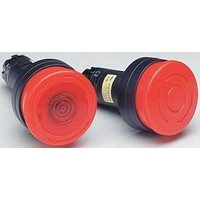
SWITCH, EMERGENCY STOP, 1NO/1NC, 600VAC
Manufacturer
IDEC
Datasheet
1.HW1B-M0.pdf
(56 pages)
Specifications of HW1E-LV4F11QD-R-24V
Contact Configuration
DPST-1NO / 1NC
Switch Operation
Pushlock Turn Reset
Contact Voltage Ac Nom
600V
Contact Voltage Dc Nom
220V
Contact Current Max
10A
Illumination Color
Red
Lead Free Status / RoHS Status
Lead free / RoHS Compliant


To build a custom selector switch, follow these steps.
Step1: How many positions of the switch are needed?
Step 2: How many contacts should there be?
Step 3: Fill in the Truth Table
Step 4: If building a 2, 4, or 5 position selector, skip this step. (2, 4, 5 position selectors have only one cam)
Step 5: Build by placing appropriate contact in appropriate mounting position for each desired row on operator cam truth
Caution: Before putting any custom selector switch into use, it should be tested using an ohmmeter.
www.idec.com
C
o
n
a
c
s
t
t
# of isolated contacts
For Operator Truth Tables, see next page.
# of positions
(maximum 6)
(2, 3, 4, 5)
1
2
3
4
5
6
(X = closed, O = open)
If building a 3 position selector, determine appropriate cam as follows:
table. “L” and “R” refer to mounting on left or right side of operator as viewed from the front of the panel.
Look at Row 1 from above table and locate an identical row in the operator truth tables (See next page).
Repeat for all rows. Find one operator that contains all rows from above table.
Record the operator cam version.
1
Oiltight Switches & Pilot Devices
2
Knob Position
(blank, S, J for 3 position)
3
Operator CAM Version
USA: (800) 262-IDEC or (408) 747-0550, Canada: (888) 317-IDEC
Custom Selector Switch Building Guide
4
5
ø22mm - HW Series
A3-79
A3
Related parts for HW1E-LV4F11QD-R-24V
Image
Part Number
Description
Manufacturer
Datasheet
Request
R

Part Number:
Description:
Cable; Between IDEC MicroSmart (port 1 or 2) and HG2F/3F/4F; 5 ft.
Manufacturer:
IDEC Corporation
Datasheet:
Part Number:
Description:
Cable; Between IDEC Micro^3C/ONC/MicroSmart (port 2) PLCs and HG2F/3F/4F; 5 ft.
Manufacturer:
IDEC Corporation
Datasheet:
Part Number:
Description:
Angled Key for Idec HS6B Safety Switch
Manufacturer:
IDEC Corporation
Datasheet:
Part Number:
Description:
Accessory, L-Shaped Key for Idec HS5B and HS5E Safety Switch
Manufacturer:
IDEC Corporation
Datasheet:
Part Number:
Description:
Accessory, Straight Key for Idec HS5B and HS5E Safety Switch
Manufacturer:
IDEC Corporation
Datasheet:
Part Number:
Description:
Straight Key for Idec HS6B Safety Switch
Manufacturer:
IDEC Corporation
Datasheet:
Part Number:
Description:
LIGHT TOWER 3 TIER RED/AMBER/GREEN 24VAC/DC WALL MOUNT
Manufacturer:
IDEC Corporation
Datasheet:
Part Number:
Description:
Flat Lens, 24V AC/DC, 1m Cable Length, Alternate: Red Green Color, IP67
Manufacturer:
IDEC Corporation
Datasheet:
Part Number:
Description:
LIGHT TOWER 2 TIER RED/GREEN 24VAC/DC WALL MOUNT
Manufacturer:
IDEC Corporation
Datasheet:
Part Number:
Description:
LIGHT TOWER 2 TIER RED/GREEN 24VAC/DC DIRECT MOUNT
Manufacturer:
IDEC Corporation
Datasheet:

Part Number:
Description:
INDICATOR INCANDESCENT LAMP, GREEN
Manufacturer:
IDEC
Datasheet:

Part Number:
Description:
LAMP, INDICATOR, INCAND, AMB
Manufacturer:
IDEC
Datasheet:
Part Number:
Description:
LAMP, INDICATOR, INCAND, GRN
Manufacturer:
IDEC
Datasheet:
Part Number:
Description:
LAMP, INDICATOR, INCAND, GRN
Manufacturer:
IDEC
Datasheet: