A165E-M-02 Omron, A165E-M-02 Datasheet - Page 8
A165E-M-02
Manufacturer Part Number
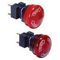
A165E-M-02
Description
SWITCH, EMERGENCY STOP, DPST-NC, 250VAC
Manufacturer
Omron
Series
A165Er
Datasheets
1.M2DA-7001.pdf
(265 pages)
2.A165E-S-02.pdf
(10 pages)
3.A165E-02.pdf
(17 pages)
4.A165E-M-02.pdf
(9 pages)
Specifications of A165E-M-02
Contact Configuration
DPST-NC
Switch Operation
Pushlock Turn Reset
Contact Voltage Ac Nom
250V
Contact Voltage Dc Nom
30V
Contact Current Max
5A
Actuator Style
Round
Switch Terminals
Solder
Actuator Length
20mm
Ip Rating
IP65
Pole Throw Configuration
DPST
Switch Function Configuration
N.C.
Current Rating (max)
5A
Operating Temp Range
-10C to 55C
Contact Form
DPST - NC
Actuator Diameter
40mm
Svhc
No SVHC
Rohs Compliant
Yes
Lead Free Status / RoHS Status
Lead free / RoHS Compliant
Lead Free Status / RoHS Status
Lead free / RoHS Compliant, Lead free / RoHS Compliant


A165E
Installation
After installing the Pushbutton, snap in the Switch from the back of the panel.
1.
Attach rubber packing or the Yellow Plate onto the Switch from its terminal side. Insert the Switch into the panel from the front. Install the lock
ring and mounting nut from the terminal side and tighten.
Adjust the slits on the hole of rubber packing and Yellow Plate to the protruding part of the Unit.
Rubber packing is not necessary when the Yellow Plate is used.
Tighten the nut to the torque of 0.29 to 0.49 N m.
Case should be installed with its protruding part adjusted to the slit of the panel hole.
Align the lock ring to the groove of the case so that the edge is drawn to the panel side.
2.
Snap on the Switch to the Pushbutton.
Make sure that the Switch has the correct orientation when snap-
ping it onto the Pushbutton. Align the white dot on the Pushbutton
with the guide groove on the side of the Switch marked with an “L” as
shown below, and push the Switch into the Pushbutton until it clicks
into place. Confirm that the Switch is securely in place before using.
Mounting to the Panel
Installing the Switch
Mounting the Switch
Lock hole
Cutout
Lock
White dot
Guide groove
L marking
Mounting nut
Rubber packing
(included with the
product) or Yellow
Plate (sold separately)
Lock ring
Panel
3.
Insert the prongs of the A16Z-5080 Extractor between the Switch
and the Pushbutton, grip the Switch, and pull to remove.
4.
When mounting the Lamp, make sure it is facing the direction shown
in the following diagram. Insert the Lamp while matching the pro-
truding part of the Lamp and the small guides on the outer surface of
the case.
Removing the Switch
Installing the LED Lamp
Rubber packing or Yellow Plate (sold separately)
Protruding part
Panel
Edge
Extractor
(A16Z-5080)
Mounting nut
Lock ring
A165E
115
Related parts for A165E-M-02
Image
Part Number
Description
Manufacturer
Datasheet
Request
R

Part Number:
Description:
ESTOP OPERATOR
Manufacturer:
Omron
Datasheet:
Part Number:
Description:
E-stop,non-lighted,1NC,40diamt
Manufacturer:
Omron
Datasheet:

Part Number:
Description:
E-stop,non-lighted,40diameter
Manufacturer:
Omron
Datasheet:
Part Number:
Description:
ESTOP OPERATOR
Manufacturer:
Omron
Datasheet:
Part Number:
Description:
1 NC CONTACT
Manufacturer:
Omron
Datasheet:

Part Number:
Description:
2 NC CONTACTS
Manufacturer:
Omron
Datasheet:
Part Number:
Description:
2 NC CONTACTS
Manufacturer:
Omron
Datasheet:
Part Number:
Description:
ESTOP OPERATOR
Manufacturer:
Omron
Datasheet:
Part Number:
Description:
E-stop,lighted,1NC,40diameter
Manufacturer:
Omron
Datasheet:
Part Number:
Description:
E-stop,lighted,2NC,40diameter
Manufacturer:
Omron
Datasheet:

Part Number:
Description:
SWITCH PB SQUARE MOM SPDT GREEN
Manufacturer:
Omron
Datasheet:
Part Number:
Description:
SWITCH PB SQUARE MOM SPDT WHITE
Manufacturer:
Omron
Datasheet:
Part Number:
Description:
SWITCH PB SQUARE MOM SPDT YELLOW
Manufacturer:
Omron
Datasheet:
Part Number:
Description:
SWITCH PB RECTANG MOM SPDT BLUE
Manufacturer:
Omron
Datasheet:
Part Number:
Description:
SWITCH PB RECTANG MOM SPDT YEL
Manufacturer:
Omron
Datasheet: