67121K506X Switchcraft Inc., 67121K506X Datasheet - Page 84
67121K506X
Manufacturer Part Number
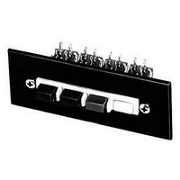
67121K506X
Description
SWITCH, MULTI-STATION, 12, DPDT 3A SCREW
Manufacturer
Switchcraft Inc.
Series
67000r
Type
Illuminatedr
Datasheet
1.65041K206X.pdf
(333 pages)
Specifications of 67121K506X
No. Of Stations
12
Contact Configuration
DPDT
Contact Current Max
3A
Contact Voltage Ac Nom
125V
Contact Voltage Dc Nom
125V
Switch Terminals
Solder Lug
Circuitry
DPDT
Rohs Information
Switchcraft RoHS Info.
Circuit
DPDT
Switch Function
-
Contact Rating @ Voltage
3A @ 125VAC
Actuator Type
Square Button
Illumination Type, Color
-
Illumination Voltage (nominal)
-
Mounting Type
Panel Mount
Termination Style
Solder Lug
Lead Free Status / RoHS Status
Lead free / RoHS Compliant


FAX: 773 792 - 2129
SWITCHCRAFT, INC. 5555 N. Elston Ave. • Chicago, IL 60630
Single open circuit. (J1.)
Transfer circuit. (J5).
Single closed. Isolated
switching “make”
circuit. (J4-1A).
JACK SCHEMATICS
Circuit Types: Jacks normally have through circuits, shunt
circuits, and/or isolated switching circuits, either individually or
in various combinations. The chart below shows schematics of
39 common jacks - many more combinations are possible, but
these are the most commonly used. A basic description of the
switching action of each jack accompanies each schematic.
Military Identification: Military specifications covering phone
jacks use a special code to describe jack functions. Jack
schematic descriptions are coded J-1 through J-13 (as
appropriate) to coincide with Federal Item Identification
Guides for Supply Cataloging. One or more groups of suffix
numbers/letters identify isolated switching circuits used.
Suffixes identify the switching by industry recognized notation,
i.e., 1-A, 1-B, 1-C, 1-D, etc. See chart below.
Double open circuit.
Isolated switching–
separate “break” and
make circuits (J2-1A-1B).
Double open circuit.
Isolated switching–
separate “make”
circuits on both tip and
ring. (J2-2A).
* Please visit the product pages on our website for the most up-to-date product information
Single closed circuit,
sleeve common. (J3).
Tip closed, ring
open. (J10).
Double closed
circuit. (J7).
Single closed circuit
Isolated switching
“break” circuit. (J4-1B).
Double closed circuit.
Isolated switching
“make” circuit on ring
spring. (J7-1A).
DIMENSIONS ARE FOR REFERENCE ONLY
Single closed circuit. (J4).
Tip closed, ring open
(common to sleeve). (J6).
Single closed circuit.
Isolated switching
transfer circuit. (J4-1C).
Single closed circuit–
“make” before
“break”. (J8).
Single closed circuit
plus “make” before
“break”. Isolated
switching–“make”
before “break”
circuit. (J8-1D).
NOTE: Number indicates the quantity of circuit - 2-A means 2, A circuits.
Terminals locations shown on jack schematics do not necessarily coincide
with physical locations on jacks. Not all circuit types available on all jacks.
Notation
1-A
1-B
1-C
1-D
(mm)
Inch
Double open circuit. (J2).
Single open circuit.
Isolated switching
“break” circuit. (J1-1B).
Double closed circuit.
Isolated switching
“break” circuit. (J7-1B).
Single open circuit.
Isolated switching
transfer circuit. (J1-1C).
Single open circuit.
Isolated switching–
separate transfer and
“make” circuits.
(J1-1A-1C).
One, SPST switching circuit. Also known as NO
(normally open) or “make” circuit.
One, SPST switching circuit. Also known as NC
(normally closed) or “break” circuit.
One, SPDT switching circuit. Also known as transfer
or “break” before “make” circuit.
One, SPDT switching circuit. Also known as “make”
before “break” circuit.
Meaning
JACKS AND PLUGS
JACK SCHEMATICS
JACK SCHEMATICS
Single open circuit.
Isolated switching
“make” circuit. (J1-1-A).
Double closed circuit,
ring common to
sleeve. (J13).
Double open circuit.
Isolated switching
transfer circuit. (J2-1C).
Double open circuit.
Isolated switching
“make” circuit.
(J2-1A).
Single closed circuit.
Isolated switching
“break” circuit. Sleeve
common to isolated
switching circuit throw.
(J4-1B).
79
Related parts for 67121K506X
Image
Part Number
Description
Manufacturer
Datasheet
Request
R

Part Number:
Description:
ADAPTER F RT ANG MALE/FEMALE
Manufacturer:
Pomona Electronics
Datasheet:

Part Number:
Description:
INDUCTOR TOROID W/HDR 150UH 15%
Manufacturer:
JW Miller A Bourns Company
Datasheet:

Part Number:
Description:
CONN PLUG PHONE 1/4" 2POS RED
Manufacturer:
Switchcraft Inc.
Datasheet:

Part Number:
Description:
CONN PLUG 2-COND 1/4" PHONE SLD
Manufacturer:
Switchcraft Inc.
Datasheet:

Part Number:
Description:
CONN PLUG PHONE SILENT 2-COND
Manufacturer:
Switchcraft Inc.
Datasheet:

Part Number:
Description:
THICK PANEL/GOLD PLA
Manufacturer:
Switchcraft Inc.
Datasheet:

Part Number:
Description:
CONN JACK PHONE 1/4" 2POS CLOSED
Manufacturer:
Switchcraft Inc.
Datasheet:

Part Number:
Description:
PHONE HI-D JACK .25" 2COND SLD
Manufacturer:
Switchcraft Inc.
Datasheet:

Part Number:
Description:
ADAPTER PHONO PLUG - A3M
Manufacturer:
Switchcraft Inc.
Datasheet:

Part Number:
Description:
SWITCH PB MOM RED PNL MT W/HDWR
Manufacturer:
Switchcraft Inc.
Datasheet:

Part Number:
Description:
SWITCH PB 1-CIR REAR MT BLACK
Manufacturer:
Switchcraft Inc.
Datasheet:
Part Number:
Description:
SWITCH PB MOM RED SPDT PANEL MNT
Manufacturer:
Switchcraft Inc.
Datasheet:
Part Number:
Description:
SWITCH PUSHB 1-A SLD LUG RED
Manufacturer:
Switchcraft Inc.
Datasheet:

Part Number:
Description:
SWITCH PB MOM PHONO JACK TERM
Manufacturer:
Switchcraft Inc.
Datasheet:
