V-10G5-1C25-K Omron, V-10G5-1C25-K Datasheet - Page 14
V-10G5-1C25-K
Manufacturer Part Number
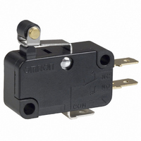
V-10G5-1C25-K
Description
MICRO SWITCH, ROLLER LEVER SPDT 10A 250V
Manufacturer
Omron
Series
Vr
Type
Snap Actionr
Specifications of V-10G5-1C25-K
Microswitch Type
Snap Action
Actuator Style
Hinge Roller Lever
Operating Force Max
200gf
Contact Voltage Ac Nom
250V
Contact Voltage Dc Nom
250V
Contact Current Max
10A
Circuit
SPDT
Switch Function
On-Mom
Contact Rating @ Voltage
10A @ 250VAC
Actuator Type
Lever, Roller
Mounting Type
Chassis Mount
Termination Style
Quick Connect - .187" (4.7mm)
Operating Force
240gf
Contact Form
SPDT
Contact Rating
10 Amps
Actuator
Hinge Roller Lever
Body Style
Miniature
Current, Rating
10 A
Dielectric Strength
1500 VAC
Material, Casing
Thermoset
Number Of Poles
1
Operation
Snap Action
Special Features
Short Hinge
Standards
UL Recognized, CSA Certified, RoHS Compliant
Temperature Rating
-25 to +80 °C
Termination
Quick Connect
Voltage, Rating
250 V
Lead Free Status / RoHS Status
Lead free / RoHS Compliant
Lead Free Status / RoHS Status
Lead free / RoHS Compliant, Lead free / RoHS Compliant
Other names
SW128
V-10G5-1C25-KBYOMI
V10G51C25K
V10G51C25KBYOMI
V-10G5-1C25-KBYOMI
V10G51C25K
V10G51C25KBYOMI


Precautions
Be sure to read the precautions and information common to all Snap Action and Detection Switches, contained in the Technical User’s Guide,
“Snap Action Switches, Technical Information” for correct use.
■ Correct Use
Terminal Connection
To solder the lead to the solder terminal, apply a soldering iron rated
at 60 W max. quickly (within 5 seconds) with the actuator at the free
position.
Note that applying a soldering iron for too long a time or using one
that is rated at more than 60 W may degrade the switch characteris-
tics.
Use an appropriate mating connector for #187 or #250 quick connect
terminals.
Specifications Approved by TÜV Rheinland
According to EN61058-1
Appropriate Cable Size (mm
Operation
Make sure that the operating body pushes the switch actuator with
an adequate force when the switch is to be operated, and that it does
not touch the actuator when the switch is released.
Do not change the operating position by modifying the actuator.
Do not use the switch in a application where the operating speed is
extremely slow or the actuator is set in the midpoint between the free
position and operating position.
Install the pin plunger switch so that the operating force is applied in
alignment with the stroke of the actuator. The switch should be set so
that its stroke is in the range of 60 to 90% of the rated OT (minimum
value) when the switch has been operated.
134
Model
V-10
V-15
Snap Action Switch
2
)
Solder terminal
0.75, 1.25, 2.0
1.25, 2.0
V
■ Cautions
Insulation Distance
According to EN61058-1, the minimum insulation thickness for this
switch should be 1.1 mm and minimum clearance distance between
the terminal and mounting plate should be 1.0 mm. If the insulation
distance cannot be provided in the product incorporating the switch,
either use a switch with insulation barrier or use a separator to
ensure sufficient insulation distance.
Related parts for V-10G5-1C25-K
Image
Part Number
Description
Manufacturer
Datasheet
Request
R

Part Number:
Description:
SWITCH ROLLER SPDT 10A .187QC
Manufacturer:
Omron
Datasheet:

Part Number:
Description:
MINIATURE BASIC SWITCH
Manufacturer:
Omron
Datasheet:

Part Number:
Description:
MINIATURE BASIC SWITCH
Manufacturer:
Omron
Datasheet:
Part Number:
Description:
MINIATURE BASIC SWITCH
Manufacturer:
Omron
Datasheet:
Part Number:
Description:
MINIATURE BASIC SWITCH
Manufacturer:
Omron
Datasheet:

Part Number:
Description:
SWITCH BASIC SPDT 10A 100GF
Manufacturer:
Omron
Datasheet:

Part Number:
Description:
SWITCH BASIC SPDT 10A .187QC
Manufacturer:
Omron
Datasheet:
Part Number:
Description:
MINIATURE BASIC SWITCH
Manufacturer:
Omron
Datasheet:
Part Number:
Description:
SWITCH MINI SPDT 10A PIN PLNGR
Manufacturer:
Omron
Datasheet:
Part Number:
Description:
SWITCH MINI SPDT 10A PIN PLNGR
Manufacturer:
Omron
Datasheet:
Part Number:
Description:
MINIATURE BASIC SWITCH
Manufacturer:
Omron
Datasheet: